2.2 Wiring
2-8
2.2.3 Wiring precautions
Exercise caution for the following when wiring.
(1) Confirm that the supply voltage is within the input voltage range described on the rating plate.
(2) Always connect the power lines to the inverter main power input terminals L1/R, L2/S, L3/T (3 phase). (The
inverter will be damaged when power is applied while the power lines are connected to the wrong terminals.)
(3) Always route the ground line to prevent accidents such as electric shock and fire and to reduce noise.
(4) For the lines connecting to the main circuit terminals, use crimped terminals with insulating sleeves or use
crimped terminals in conjunction with insulating sleeves for high connection reliability.
(5) Separate the routing of the lines connected to the main circuit terminal input side (primary side) and the output
side (secondary side) and the lines connected to the control circuit terminals.
(6) After removing the main circuit terminal screw, always restore the terminal screw in position and tighten even
if lines are not connected.
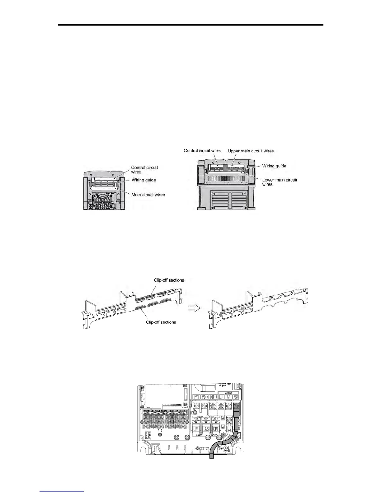
(7) The wiring guide is used to separately route the main circuit wiring and the control circuit wiring. For inverters
with a capacity of 3.7 kW or below, the main circuit wiring and the control circuit wiring can be separated. In a
capacity of 5.5 to 22 kW, the main circuit wiring (lower level), the main circuit wiring (upper level) and the
control circuit wiring can be separated. Exercise caution for the order of wiring.
Figure 2.2-5 Case of FRN3.7G1S-2J Figure 2.2-6 Case of FRN11G1S-2J
Handling the Wiring Guide
For inverters with a capacity of 11 to 22 kW (three-phase 200 V class series), the wiring space may become
insufficient when routing the main circuit wires, depending on the wire material used. In these cases, the
relevant cut-off sections (see the figure below) can be removed using a pair of nippers to secure routing space.
Be warned that removing the wiring guide to accommodate the enlarged main circuit wiring will result in
non-conformance to IP20 standards.
Before cut off After cut off
Figure 2.2-7 Wiring Guide (for FRN15G1S-2J)
(8) Depending on the inverter capacity, straight routing of the main circuit wires from the main circuit terminal
block may not be possible. In these cases, route the wires as shown in the figure below and securely attach
the front cover.
Figure 2.2-8

 Loading...


