2.2 Wiring
2-15
Chapter 2 INSTALLATION AND WIRING
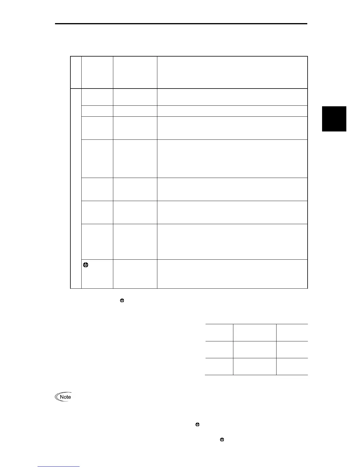
[3] Description of terminal functions (main circuit terminals)
Table 2.2-4
Classification
Symbol Name Functional description
L1/R, L2/S,
L3/T
Main circuit power
input
Connect the three-phase input power lines.
U, V, W Inverter output Connect a three-phase motor.
R0, T0
Auxiliary power
input for the
control circuit
For a backup of the control circuit power supply, connect AC
power lines same as that of the main power input. (For inverters
with 1.5 kW or above)
P1, P(+)
For direct current
reactor
connection
Connect a DC reactor (DCR) for correcting power factor.
* HD-mode inverters: A DCR is provided as option for 0.4 to 55
kW, and as standard for 75 kW or above.
LD-mode inverters: A DCR is provided as option for 5.5 to 45
kW, and as standard for 55 kW or above.
P(+), DB
For braking
resistor
connection
Connect a braking resistor (option).
P(+), N(-)
For DC link bus
connection
Connect a DC link bus of other inverter(s). A high power-factor,
regenerative PWM converter is also connectable to these
terminals.
R1, T1
Auxiliary power
input for the fans
Normally, no need to use these terminals. Use these terminals
for an auxiliary power input of the fans in a power system using
a power regenerative PWM converter (RHC series). (For 200 V
class series of inverters with 37 kW and 400 V class series with
75 kW or above)
Main circuit
G
For inverter and
motor grounding
Grounding terminals for the inverter's chassis (or case) and
motor. Earth one of the terminals and connect the other to the
grounding terminal of the motor. Inverters provide a pair of
grounding terminals that function equivalently.
(1) Inverter ground terminal G
The terminal is the ground terminal for the inverter chassis
(case). Always connect to ground for safety and as a
countermeasure for noise. To prevent accidents such as electric
shock and fire, the electric facility technical standards require
grounding construction for metallic frames in electric
instruments.
Follow the steps below in connecting the ground terminal on the
power supply side.
1) Connect to a class D grounding electrode (200 V class series)
or a class C grounding electrode (400 V class series)
according to the electric facility technical standards.
2) The grounding wire should be thick, with large surface area,
and as short as possible.
The 200 V/400 V class series of inverters (5.5 to 11 kW) with a built-in EMC filter have three grounding
terminals. To achieve more effective noise reduction, connect the ground line to the designated
grounding terminal.
( Chapter 13, Section 13.3.2 "Recommended installation method"
(2) Inverter output terminals U, V, W, motor ground terminal
G
1) Connect the 3 phase motor terminals U, V, and W while matching the phase sequence.
2) Connect the ground line of the outputs (U, V, W) to the ground terminal (
G).
Table 2.2-5 Grounding Instruments in
Compliance with the Electric Facility Technical
Standards
Power
supply
voltage
Grounding class Grounding
resistance
Three-
phase
200 V
Class D
grounding
100 Ω or
below
Three-
phase
400 V
Class C
grounding
10 Ω or
below

 Loading...


