5.4 Details of Function Codes
5-122
5.4.2 E codes (Terminal functions)
E01 to
E09
Terminal [X1] to [X9] (Function Select)
Related Function Codes: E98 Terminal [FWD] (Function Select)
E99 Terminal [REV] (Function Select)
Terminals [X1] to [X9], [FWD], and [REV] are programmable general-purpose digital input terminal.
Assignment of functions by using E01 to E09, E98, and E99 is possible.
With the negative logic setting, switching between active ON and active OFF of each signal is possible. The
factory default setting is normal logic system "Active ON." The following functions can be assigned to digital
input terminals [X1] to [X9], [FWD], and [REV]. Explanations of each function are given in Active ON logic
(normal logic). Explanation of each signal is provided in an order of assigned data. However, highly relevant
signals are collectively explained. See the function codes in the "Related function codes" column, if any.
In FRENIC-MEGA, selection of the control method is possible from V/f control, dynamic torque vector control,
V/f control with speed sensor, dynamic torque vector control with speed sensor, vector control without speed
sensor, and vector control with speed sensor. Some functions apply exclusively to the specific drive control.
In the control system field, "{: Valid" or "X: Invalid" is indicated for each function. (See page 5-3.)
- Digital input terminal has functions such as run and stop commands including Run command FWD,
Coast-to-stop command BX, and frequency setting change command. Depending on the digital input
terminal status, modifying the function code setting may cause a sudden motor start or an abrupt
change in speed. Change the setting of function code after thoroughly checking the safety.
- To the digital input terminal, the function to switch the operation method of run command and command
method of frequency setting (SS1, 2, 4, 8, Hz2/Hz1, Hz/PID, IVS, and LE) can be assigned. When
switching these signals, operation may suddenly starts or the speed changes rapidly under some
conditions.
An accident or injuries could occur.
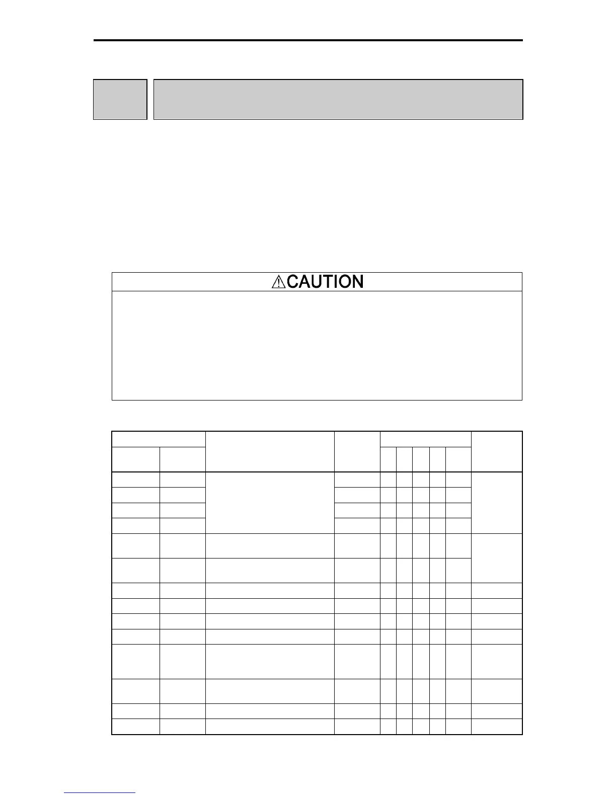
Table 5.4-62
Data Control Method
Active
ON
Active
OFF
Defined Function Signal Name
V/f
PG
V/f
PG
less
PG
Torque
Control
Related
Function
Code
0 1000 SS1 { { { { X
1 1001 SS2 { { { { X
2 1002 SS4 { { { { X
3 1003
Multi-frequency selection (0 to 15
steps)
SS8 { { { { X
C05 to C19
4 1004
Acceleration/deceleration select (2
steps)
RT1 { { { { X
5 1005
Acceleration/deceleration select (4
steps)
RT2 { { { { X
F07, F08,
E10 to E15
6 1006 Self-hold select HLD { { { { { F02
7 1007 Coast-to-stop command BX { { { { { ―
8 1008 Alarm (error) reset RST { { { { { ―
1009 9 External alarm THR { { { { { ―
10 1010 Jogging operation JOG { { { { X
C20
H54, H55,
d09 to d13
11 1011
Frequency command 2/Frequency
command 1
Hz2/Hz1 { { { { X F01, C30
12 1012 Motor select 2 M2 { { { { { A42
13 - Enable DC braking DCBRK { { { { X F20 to F22

 Loading...


