11.4 Option
11-79
Chapter 11 SELECTING PERIPHERAL EQUIPMENT
[8] Relay output interface card (OPC-G1-RY)
The relay output interface card is a relay output (1C contact) card for general output signal. It has two
independent relay outputs so that using two cards allows the user to activate up to four relay outputs.
A signal to be output to each relay output can be defined with function codes E20 to E23. Selecting "Active
OFF" with the function code enables the relay to be turned ON without relay coil excitation. This is useful
for a fail-safe application for the power system.
Applicable ports
A FRENIC-MEGA inverter has three option connection ports. Note that each port has some limitations as
shown below.
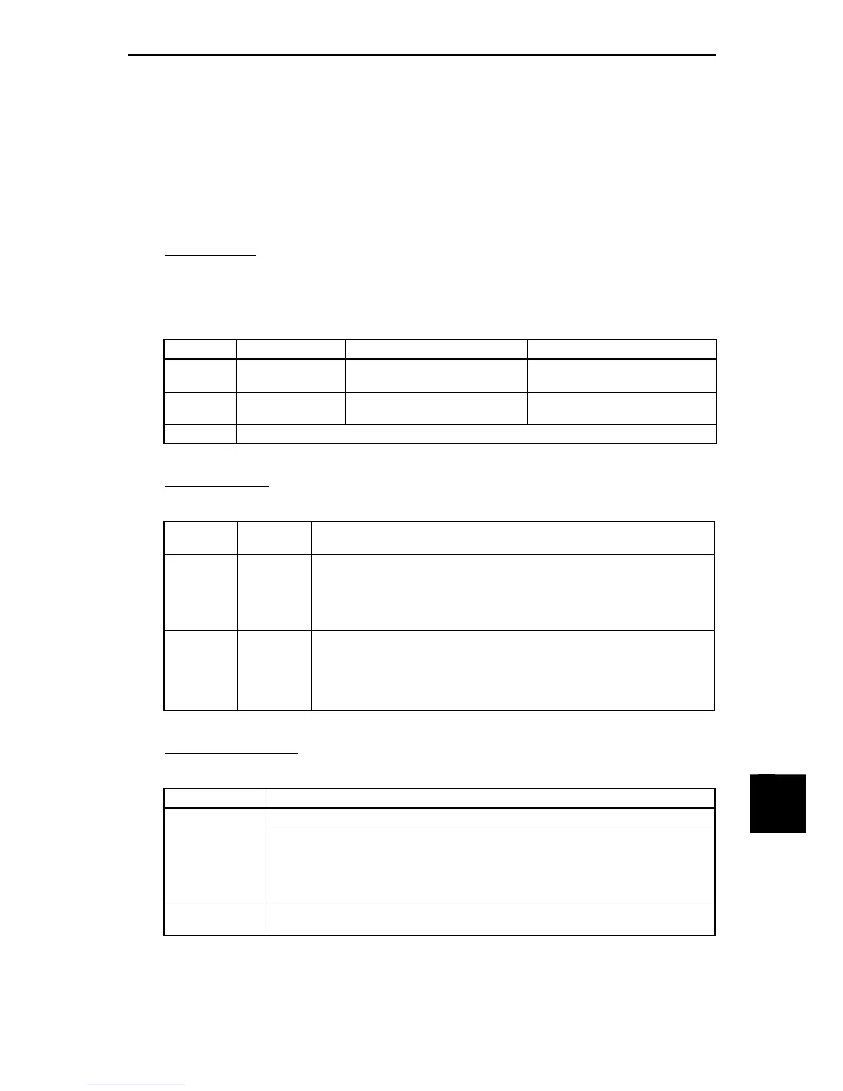
Table 11.4-47
Port Output signals Assignment Notes
A-port
Relay output 1
Relay output 2
Function code E20 (Y1 output)
Function code E21 (Y2 output)
Do not connect this card to the
inverter's terminal [Y1] or [Y2].
B-port
Relay output 1
Relay output 2
Function code E22 (Y3 output)
Function code E23 (Y4 output)
Do not connect this card to the
inverter's terminal [Y3] or [Y4].
C-port Not available for the relay output interface card
Terminal functions
Table 11.4-48
Terminal
Signal
Name Function
[1A]
[1B]
[1C]
Relay
output 1
Relay contacts to output signals selected by function codes E20 and E22,
such as Inverter Running, Frequency Arrival and Overload Early Warning.
In "active ON", the contact [1A] - [1C] closes and [1B] - [1C] opens while
the signal is active.
[2A]
[2B]
[2C]
Relay
output 2
Relay contacts to output signals selected by function codes E21 and E23,
such as Inverter Running, Frequency Arrival and Overload Early Warning.
In "active ON", the contact [1A] - [1C] closes and [1B] - [1C] opens while
the signal is active.
Electrical specifications
Table 11.4-49
Item Specifications
Contact capacity 250 VAC 0.3 A COSΦ = 0.3 or 48 VDC 0.5 A (resistor load)
Contact life 250 VAC 0.3 A :200,000 times (ON/OFF every 1 second)
48 VDC 0.5 A :200,000 times (ON/OFF every 1 second)
Note: When frequent ON/OFF switching is anticipated (for example, when using
the current limit function with the inverter output limiting signal), use the
terminals [Y1] to [Y4] (transistor outputs) instead.
Applicable
safety standards
EN61800-5-1:2007, Overvoltage Category II (Reinforced Insulation) 250 VAC class

 Loading...


