1.6 Precautions for Using Inverters
1-25
Chapter 1 BEFORE USE
Wiring precautions
(1) Route the wiring of the control circuit terminals as far from the wiring of the main circuit as possible.
Otherwise electric noise may cause malfunctions.
(2) Fix the control circuit wires inside the inverter to keep them away from the live parts of the main
circuit (such as the terminal block of the main circuit).
(3) If more than one motor is to be connected to a single inverter, the wiring length should be the total
length of wiring between the inverter and motors.
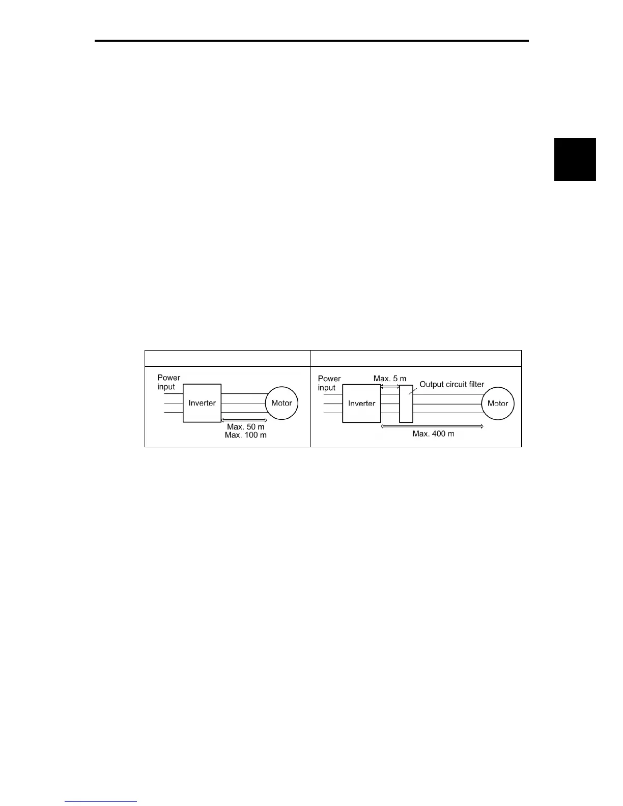
(4) Precautions for high frequency leakage currents
If the wiring distance between an inverter and a motor is long, high frequency currents flowing
through stray capacitance across wires of phases may cause an inverter overheat, overcurrent trip,
increase of leakage current, or it may not assure the accuracy in measuring leakage current.
Depending on the operating condition, an excessive leakage current may damage the inverter. To
avoid the above problems when directly connecting an inverter to a motor, keep the wiring distance
50 m or less for inverters with a capacity of 3.7 kW or below, and 100 m or less for inverters with a
higher capacity.
If the wiring distance longer than the specified above is required, lower the carrier frequency or insert
an output circuit filter (OFL--A).
When the inverter drives two or more motors connected in parallel (group drive), in particular, using
shielded wires, the stray capacitance to the earth is large, so lower the carrier frequency or insert an
output circuit filter (OFL--A).
Table 1.6-5
No output circuit filter installed Output circuit filter installed
For an inverter with an output circuit filter installed, the total secondary wiring length should be 400 m
or less (100 m or less under the vector control).
If further longer secondary wiring is required, consult your Fuji Electric representative.
(5) Precautions for surge voltage in driving a motor by an inverter (especially for 400 V class,
general-purpose motors)
If the motor is driven by a PWM-type inverter, surge voltage generated by switching the inverter
component may be superimposed on the output voltage and may be applied to the motor terminals.
Particularly if the wiring length is long, the surge voltage may deteriorate the insulation resistance of
the motor. Implement any of the following measures.
• Use a motor with insulation that withstands the surge voltage. (All Fuji standard motors feature
reinforced insulation.)
• Connect a surge suppressor unit (SSU50/100TA-NS) at the motor terminal.
• Connect an output circuit filter (OFL--A) to the output terminals (secondary circuits) of the
inverter.
• Minimize the wiring length between the inverter and motor (10 to 20 m or less).
(6) When an output circuit filter is inserted in the secondary circuit or the wiring between the inverter and
the motor is long, a voltage loss occurs due to reactance of the filter or wiring, so that insufficient
voltage may cause output current oscillation or a lack of motor output torque. To avoid it, select the
constant torque load by setting the function code F37 (Load Selection/Auto Torque Boost/Auto
Energy Saving Operation) to "1" and keep the inverter output voltage at a higher level by configuring
H50 (Non-linear V/f Pattern, Frequency) and H51 (Non-linear V/f Pattern, Voltage).

 Loading...


