2.2 Wiring
2-7
Chapter 2 INSTALLATION AND WIRING
2.2.2 Removing and mounting the front cover and the wiring guide
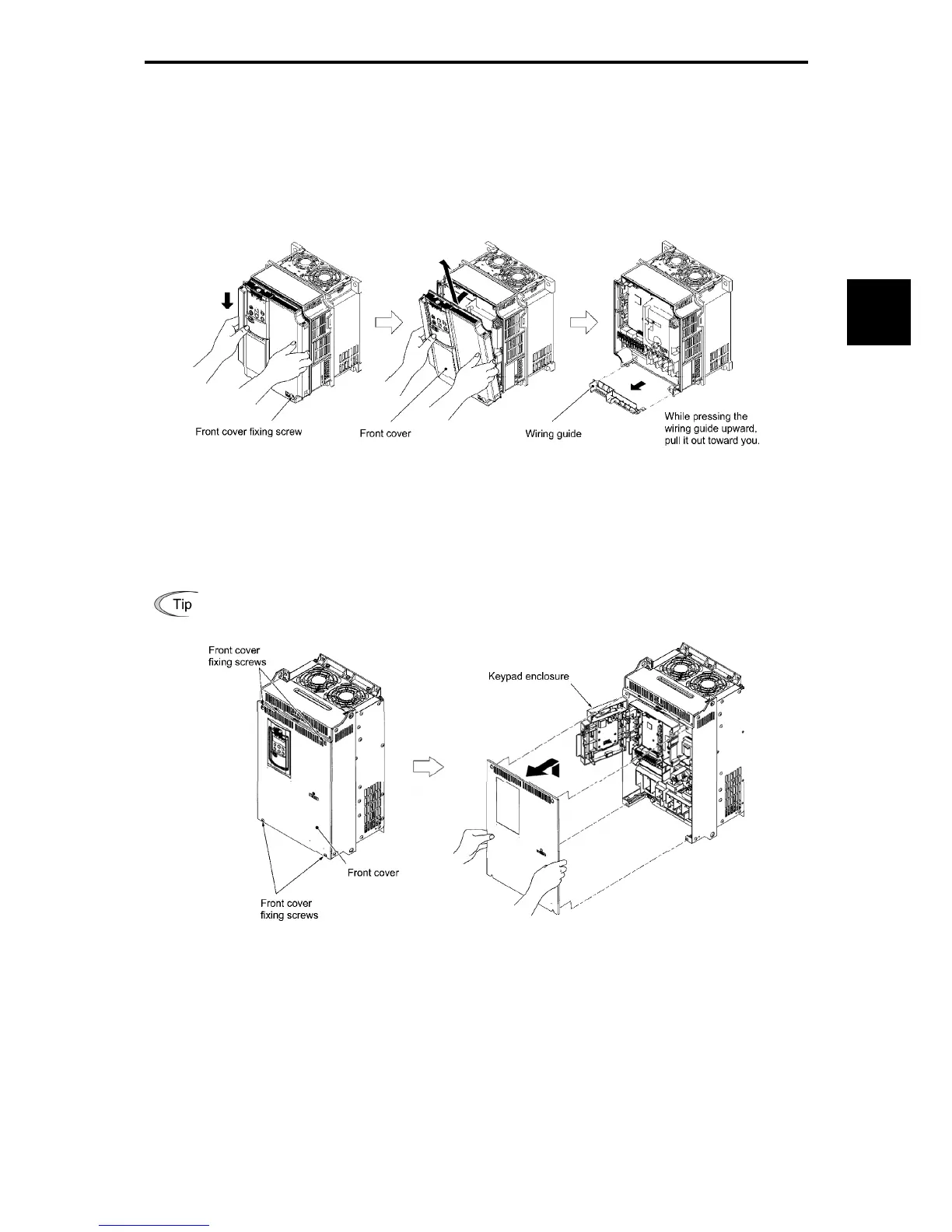
(1) Types with a capacity of 22 kW or below
1) Loosen the screws of the front cover. Hold both sides of the front cover with the hands, slide the cover
downward, and pull. Then remove to the upward direction.
2) Push the wiring guide upward and pull. Let the guide slide and remove.
3) After routing the wires, attach the wiring guide and the front cover reversing the steps above.
Figure 2.2-3 Removal of the Front Cover and the Wiring Guide (for FRN11G1S-2J)
(2) Types with a capacity of 30 to 630 kW
1) Loosen the screws of the front cover. Hold both sides of the front cover with the hands and slide upward to
remove.
2) After routing the wires, align the front cover top edge to the screw holes and attach the cover reversing the
steps in figure 2.2-4.
Open the keypad enclosure to view the control printed circuit board.
Tightening torque: 1.8 N•m (M4)
3.5 N•m (M5)
Figure 2.2-4 Removal of the Front Cover (for FRN30G1S-2J)

 Loading...


