5.4 Details of Function Codes
5-211
Details of
Function Codes
F codes
E codes
C codes
P codes
H98
A42
b42
r42
J codes
d codes
U codes
y codes
Chapter 5 Function Code
5.4.6 A code (Motor 2 parameter)
b code (Motor 3 parameter)
r code (Motor 4 parameter)
In FRENIC-MEGA, changing the control method during an operation is possible, which includes the operation of
one inverter with switching operations between four motors, and on/off of energy-saving operations accompanied
by switching stages by changing inertia moment of the machine by gear switching of one motor.
Table 5.4-145
Function Code Type Remarks
F/E/P and other codes Motor 1 Including function codes commonly applied to motors 1 to 4.
A codes Motor 2
b codes Motor 3
r codes Motor 4
This manual describes function codes applied to motor 1 only. For the function codes of motor 2 to 4,
see the function codes of corresponding motor 1 on Table 5.4-148 on the next page. However, function
codes of motor/parameter switching 2 to 4 (A42/b42/r42) are excluded.
A42, b42
r42
Motor/Parameter Switching 2, 3, 4 (Operation Selection)
Related Function Code: d25 ASR Switching Time
A42, b42 or r42 selects whether the combination of terminal commands
M2, M3 and M4 switches the actual
motors (to the 2nd, 3rd, and 4th motors) or the particular parameters (A codes, b codes, or r codes).
Table 5.4-146
Data for
A42, b42 or r42
Function
Switching is
possible:
0 Motor switching: Switch to the 2nd motor to 4th motor Only when the
inverter is stopped
1 Parameter switching: Switching of controlling function code data
on the same motor such as turning on/off of the energy-saving
operation and PI change in the speed control system
Even when the
inverter is running.
The combination of digital input terminal commands
M2, M3 and M4 switches to any of the 1st to 4th motors.
When the motor is switched, the function code group with which the inverter drives the motor is also
switched to the one corresponding to the motor.
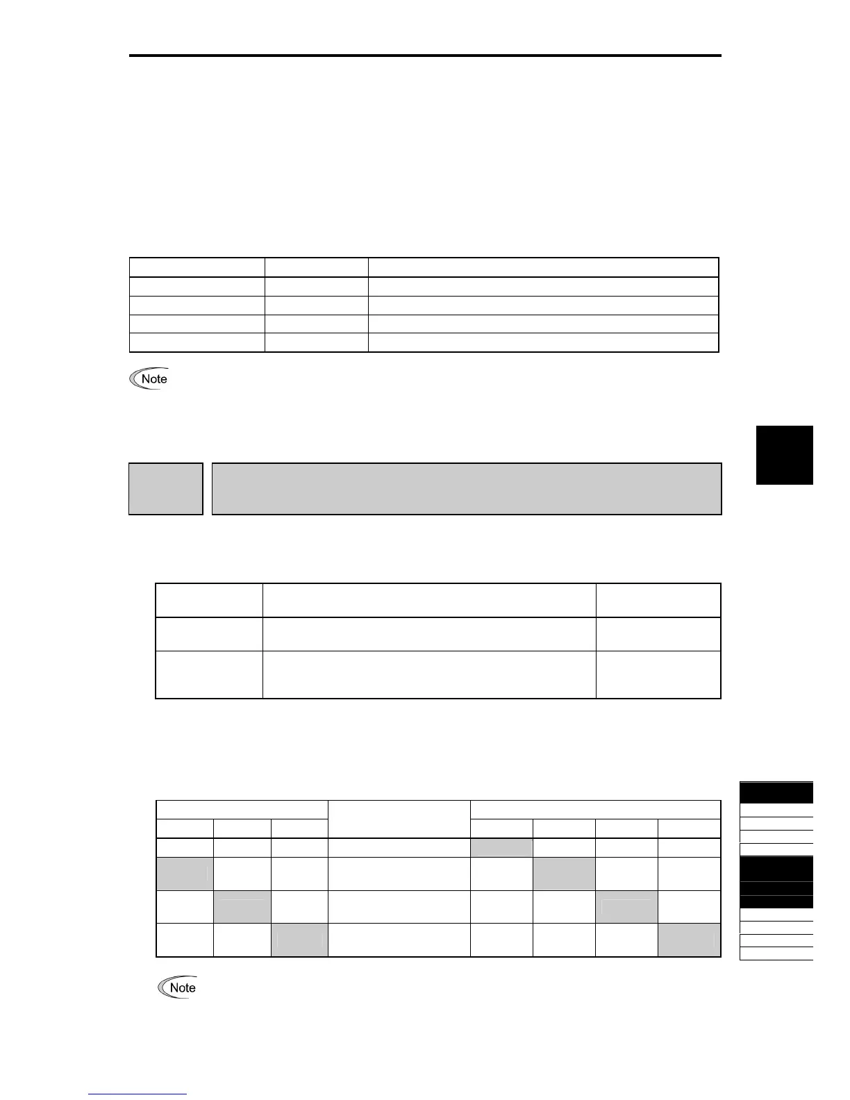
Table 5.4-147
Input Signal Output Signal
M2 M3 M4
Selected Motor
SWM1 SWM2 SWM3 SWM4
OFF OFF OFF 1st motor ON OFF OFF OFF
ON - -
2nd motor
(A code effective)
OFF ON OFF OFF
OFF ON -
3rd motor
(b code effective)
OFF OFF ON OFF
OFF OFF ON
4th motor
(r code effective)
OFF OFF OFF ON
From the point of view of signal timing, a combination of
M2, M3 and M4 must be determined at
least 2 ms before the signal of a run command is established.

 Loading...


