2.3 Attachment and Connection of Keypad
2-37
Chapter 2 INSTALLATION AND WIRING
2.3 Attachment and Connection of Keypad
You can remove the keypad from the inverter main body to mount it on the board or remotely control it at hand.
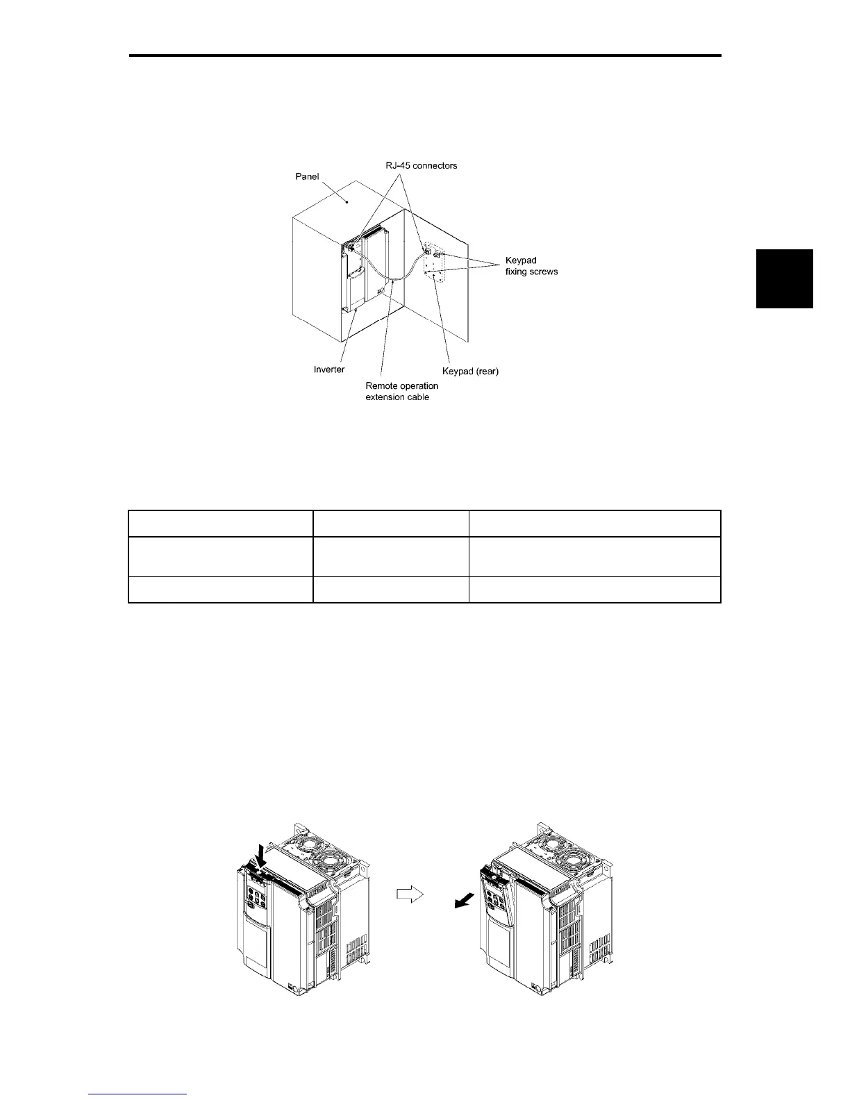
Figure2.3-1 Attaching the Keypad on the Board
The following parts are necessary when attaching the keypad to locations other than the inverter main body.
Table 2.3-1
Part name Type Remarks
Extension cable for remote
operation (Note 1)
CB-5S, CB-3S, CB-1S Three lengths available (5 m, 3 m, 1 m)
Keypad attachment screw M3x (Note 2) 2 screws required (prepared by user)
(Note 1)
When using a commercially available LAN cable, use 10BASE-T/100BASE-TX straight cables (below 20
m) which meet the ANSI/TIA/EIA-568A category 5 standards of U.S.A.
Recommended LAN cable
Manufacturer: Sanwa Supply, Inc.
Type: KB-10T5-01K (for 1 m)
KB-STP-01K (for 1 m) (shielded cable)
(Note 2)
When attaching to the board, use attachment screws with a length appropriate for the board thickness.
(The depth of threaded holes in the keypad is 11 mm)
How to remove and attach the keypad
To remove the keypad, keep the hook pressed in the direction of the arrow and pull the keypad toward you. To
attach the keypad, reverse the steps.
Figure 2.3-2 Removal of the Keypad

 Loading...


