10.1 Selecting Motors and Inverters
10-7
Chapter 10 SELECTING OPTIMAL MOTOR AND INVERTER CAPACITIES
10.1.3 Equations for selections
[1] Load torque during constant speed running
[1] General equation
The frictional force acting on a horizontally moved load must be calculated. Calculation for driving a load
along a straight line with the motor is shown below.
Where the force to move a load linearly at constant speed υ (m/s) is F (N) and the motor speed for driving
this is N
M
(r/min), the required motor output torque τ
M
(N·m) is as follows:
60 • υ F
τ
M
=
2π • N
M
•
η
G
(N • m) (10.1)
where, η
G
is Reduction-gear efficiency.
When the inverter brakes the motor, efficiency works inversely, so the required motor torque τ
M
(N • m)
should be calculated as follows:
60 • υ
τ
M
=
2π • N
M
• F • η
G
(N • m) (10.2)
(60·υ) / (2π· N
M
) in the above equation is an equivalent turning radius corresponding to speedυ (m/s)
around the motor shaft.
The value F (N) in the above equations depends on the load type.
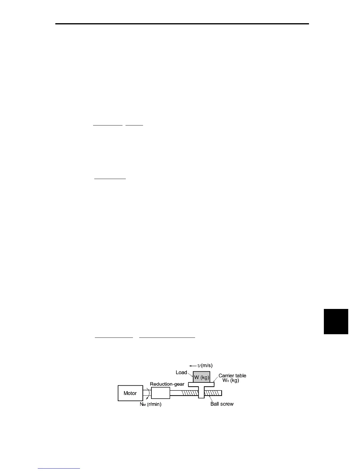
[2] Obtaining the required force F
Moving a load horizontally
A simplified mechanical configuration is assumed as shown in Figure 10.1-7. If the mass of the carrier
table is W
0
(kg), the load is W (kg), and the friction coefficient of the ball screw is μ, then the friction force F
(N) is expressed as follows, which is equal to a required force for driving the load:
F = (W
0
+ W) • g • μ (N) (10.3)
where, g is the gravity acceleration (≈ 9.8 (m/s
2
)).
Then, the driving torque around the motor shaft is expressed as follows:
Figure 10.1-7 Moving a Load Horizontally
60 • υ (W
O
+ W) • g • μ
τ
M
=
2π • N
M
•
η
G
(N • m) (10.4)

 Loading...


