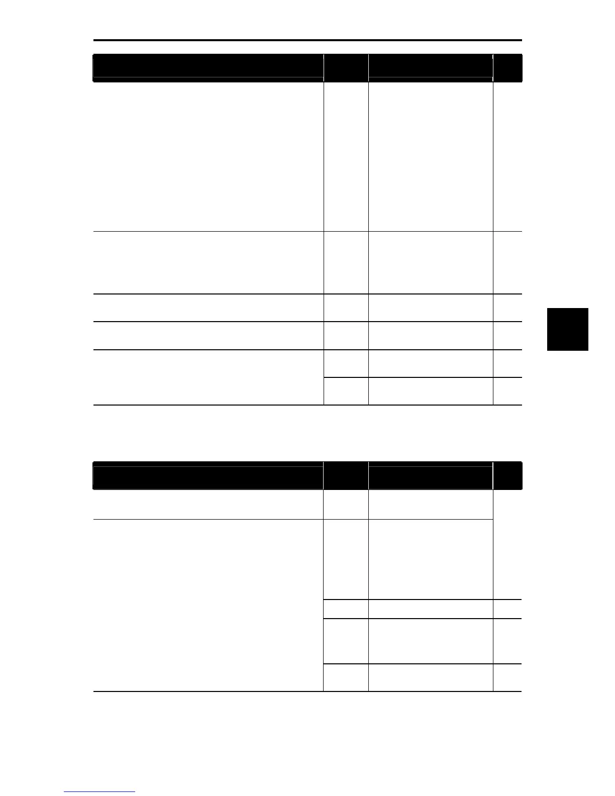
5.3 Code Index by Purpose
5-55
Chapter 5 Function Code
To:
Function
code
Name
Refer to
page:
Specify communications conditions.
y11
y12
y13
y14
y15
y16
y17
y18
y19
y20
SW2
RS-485 Communication 2
(Station address)
(Communications error
processing)
(Timer)
(Baud rate)
(Data length)
(Parity bit selection)
(Stop bit selection)
(No-response error detection
time)
(Response interval)
(Protocol selection)
< Switching the terminating
resistor of the RS-485
communications port 2 >
5-272
2-34
Specify the sources of run and frequency commands.
H30
y98
y99
Communications Link Function
(Mode selection)
Bus Link Function (Mode
selection)
Loader Link Function (Mode
selection)
5-191
5-276
Change function code data frequently via the communications link. y97
Communication Data Storage
Selection
5-275
Switch between frequency or run commands via the
communications link.
E01 to E09
Terminal [X1] to [X9] Functions
(LE)
5-122
E01 to E09
Terminal [X1] to [X9] Functions
(U-DI)
5-122
Use inverter input/output signals as general-purpose DI/DO.
E20 to E24
Terminal [Y1] to [Y5A/C]
Functions (U-DO)
5-141
5.3.16 Using the customizable logic
Table 5.3-23
To:
Function
code
Name
Refer to
page:
Enable the sequence configured by the customizable logic
function.
*2
U00
Customizable Logic
(Mode selection)
U01 to U50
U71 to U75
U81 to U85
U91
Customizable Logic: Steps 1 to
10 (Mode selection)
Customizable Logic Output
Signals 1 to 5 (Output selection)
Customizable Logic Output
Signals 1 to 5 (Function
selection) Customizable Logic
Timer Monitor (Step selection)
5-249
E01 to E09 Terminal [X1] to [X9] Functions 5-122
E20-E27
Terminal [Y1] to [Y4] Functions
Terminal [Y5A/C] Function
Terminal [30A/B/C] Function
(Relay output)
5-141
Form a logic circuit for digital input/output signals, modify them
arbitrarily, and configure a simple relay sequence inside the
inverter.
*2
E98, E99 Terminal [FWD], [REV] Functions
5-122
5-165
*2 Available for inverters with ROM version 1000 or later.

 Loading...


