7.3 List of Periodic Replacement Parts
7-4
7.3 List of Periodic Replacement Parts
Each part of the inverter has its own service life that will vary according to the environmental and operating
conditions. It is recommended that the following parts be replaced at the intervals specified in Table 7.3-1.
When replacement is necessary, consult your Fuji Electric representative.
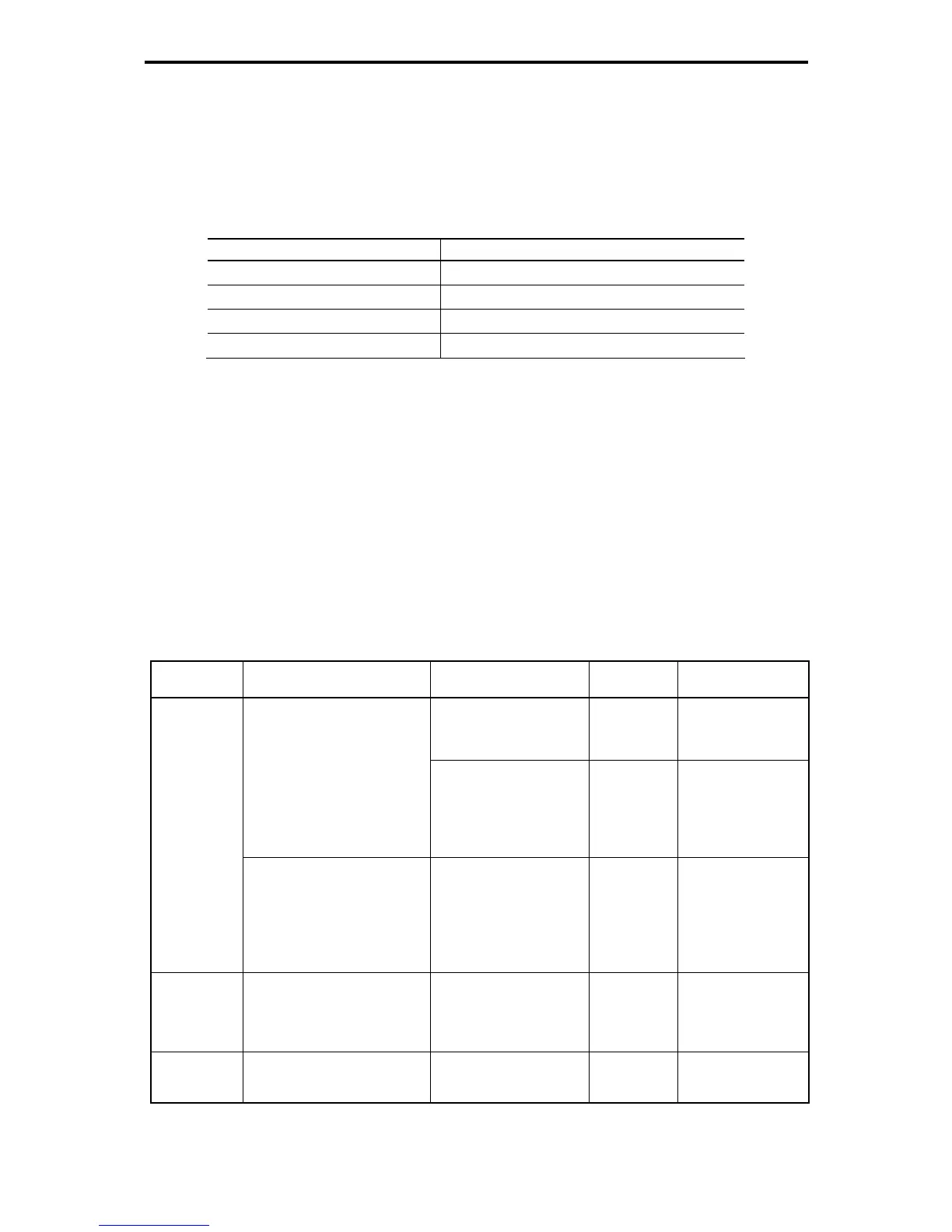
Table 7.3-1 Replacement Parts
Part name Standard replacement intervals (See Note below.)
Main circuit capacitor 10 years
Electrolytic capacitor on PCB 10 years
Cooling fan 10 years
Fuse 10 years (90 kW or above)
Note) • These replacement intervals are based on the inverter's service life estimated at a
surrounding temperature of 40°C at 100% (HD-mode inverters) or 80%
(MD-/LD-mode inverters) of full load. In environments with an ambient temperature
above 40°C or a large amount of dust or dirt, the replacement intervals may be
shorter.
• The replacement intervals listed above are only provided as a guide. They do not
guarantee the lifetimes of respective parts.
7.3.1 Judgment on service life
The inverter has the life prediction function for some parts which allows you to judge whether those parts
are approaching the end of their service life. The predicted values should be used only as a guide since
the actual service life is influenced by the ambient temperature and other usage environments.
Table 7.3-2 Life Prediction
Object of life
prediction
Prediction function End-of-life criteria
Prediction
timing
LED monitor
indication
85% or lower of the initial
capacitance at shipment
At periodic
inspection
H98: bit3=0
5_05
(Capacity)
Measurement of discharging
time
Measures the discharging time
of the DC link bus capacitor
when the main power is shut
down and calculates the
capacitance.
85% or lower of the
reference capacitance
under ordinary operating
conditions at the user site
(must be measured upon
introduction of the unit)
During
ordinary
operation
H98: bit3=1
5_05
(Capacity)
Main circuit
capacitor
ON-time counting
Counts the time elapsed when
the voltage is applied to the DC
link bus capacitor (ON-time
counting), while correcting it
according to the capacitance
measured above.
Exceeding 87,600 hours
(10 years)
During
ordinary
operation
5_26
(Elapsed time)
5_27
(Time remaining
before the end of life)
Electrolytic
capacitors on
PCBs
Counts the time elapsed when
the voltage is applied to the
capacitors, while correcting it
according to the surrounding
temperature.
Exceeding 87,600 hours
(10 years)
During
ordinary
operation
5_06
(Cumulative run time)
Cooling fan
Counts the run time of the
cooling fans.
Exceeding 87,600 hours
(10 years)
During
ordinary
operation
5_07
(Cumulative run time)
The service life of the DC link bus capacitor is automatically judged by the "measurement of discharging
time" or by "ON-time counting."

 Loading...


