2.2 Wiring
2-10
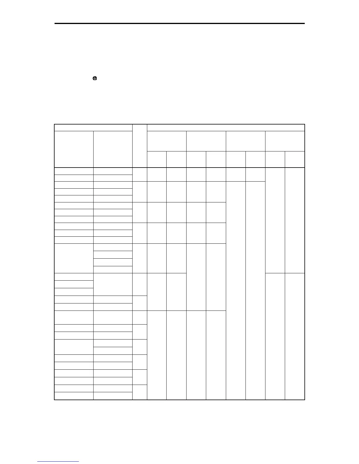
2.2.4 Main circuit terminals
[1] Screw specifications and recommended wire size (main circuit terminals)
The specifications for the screws used in the main circuit wiring and the wire sizes are shown below.
Exercise caution as the terminal layout varies by inverter capacity. In the diagram, the two ground
terminals [
G] are not differentiated for the input side (primary side) and the output side (secondary side).
Use crimp terminals covered with an insulation sleeve or with an insulation tube. The recommended wire
sizes for the main circuits are examples of using a single HIV wire (maximum allowable temperature: 75ºC)
at a surrounding temperature of 50ºC. For wire sizes when using wires of other specifications, refer to
Chapter 11, Section 11.2 "Selecting Wires and Crimp Terminals."
Table 2.2-1 Screw Specifications
Inverter type Screw specifications
Main circuit
terminals
Grounding
terminals
Auxiliary control
power input
terminals
[R0, T0]
Auxiliary fan
power input
terminals
[R1, T1]
Three-phase
200 V
Three-phase
400V
Refer
to:
Screw
size
Tightening
torque
(N·m)
Screw
size
Tightening
torque
(N·m)
Screw
size
Tightening
torque
(N·m)
Screw
size
Tightening
torque
(N·m)
FRN0.4G1-2J FRN0.4G1-4J
FRN0.75G1-2J FRN0.75G1-4J
Figure
A
M3.5 1.2 M3.5 1.2 - -
FRN1.5G1-2J FRN1.5G1-4J
FRN2.2G1-2J FRN2.2G1-4J
FRN3.7G1-2J FRN3.7G1-4J
Figure
B
M4 1.8 M4 1.8
FRN5.5G1-2J FRN5.5G1-4J
FRN7.5G1-2J FRN7.5G1-4J
FRN11G1-2J FRN11G1-4J
Figure
C
M5 3.5 M5 3.5
FRN15G1-2J FRN15G1-4J
FRN18.5G1-2J FRN18.5G1-4J
FRN22G1-2J FRN22G1-4J
Figure
D
M6 5.8 M6 5.8
FRN30G1-4J
FRN37G1-4J
FRN45G1-4J
FRN30G1-2J
FRN55G1-4J
Figure
E
M8 13.5
- -
FRN37G1-2J
FRN45G1-2J
FRN55G1-2J
FRN75G1-4J
Figure
F
-
FRN90G1-4J
-
FRN110G1-4J
Figure
G
M10 27
M8 13.5
FRN75G1-2J
-
Figure
M
-
FRN132G1-4J
-
FRN160G1-4J
Figure
H
FRN200G1-4J
FRN90G1-2J
FRN220G1-4J
Figure
I
-
FRN280G1-4J
-
FRN315G1-4J
Figure
J
-
FRN355G1-4J
-
FRN400G1-4J
Figure
K
-
FRN500G1-4J
-
FRN630G1-4J
Figure
L
M12
48
M10 27
M3.5 1.2
M3.5 1.2

 Loading...


