11.4 Option
11-69
Chapter 11 SELECTING PERIPHERAL EQUIPMENT
[5] PG interface card (OPC-G1-PG)
The PG interface card has a two-shifted pulse train (A, B, Z phase) input circuit for speed feedback and a
power output circuit for feeding power to the connected PG (pulse generator). Mounting this interface card
on the FRENIC-MEGA enables the following:
(1) Speed control (vector control with speed sensor, V/f control with speed sensor, dynamic torque
vector control with speed sensor) using PG feedback signals, and servo-lock function
(2) Pulse train input as frequency commands
Note: Using this interface card disables the pulse train frequency command via the digital input terminal
[X7] on the inverter.
Ports available for the communications card
This interface card can be connected to the C-port only, out of three option connection ports (A-, B-, and
C-ports) provided on the FRENIC-MEGA.
Applicable ROM version
This interface card is applicable to inverters having a ROM version G1S10100 or later.
PG interface specifications
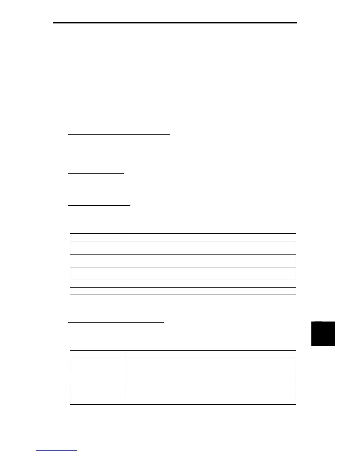
Table 11.4-34 lists PG interface specifications of this interface card.
Table 11.4-34 PG Interface Specifications
Item Specifications
Encoder pulse
resolution
20 to 3000 P/R, A-, B- and Z-phase pulse trains in incremental format
Pulse input mode
Open collector (Maximum cable length: 20 m)
Complementary (Maximum cable length: 100 m)
Pulse input voltage
High level ≥ 8 VDC Low level ≤ 3 VDC (For 12 VDC power source)
High level ≥ 10 VDC Low level ≤ 3 VDC (For 15 VDC power source)
Pulse input current 8 mA or lower
PG power supply *1 +12 VDC±10% / 120 mA or below, or +15 VDC±10% / 120 mA or below
*1
If the PG power current exceeds 120 mA, use an external power supply.
Pulse train input interface specifications
Table 11.4-35 lists pulse train input interface specifications of this interface card.
Table 11.4-35 Pulse Train Input Interface Specifications
Item Specifications
Input pulse
frequency
30 kHz max. (Open collector)
100 kHz max. (Complementary)
Pulse input mode
Open collector (Maximum cable length: 20 m)
Complementary (Maximum cable length: 100 m)
Pulse input voltage
High level ≥ 8 VDC Low level ≤ 3 VDC (For 12 VDC power source)
High level ≥ 10 VDC Low level ≤ 3 VDC (For 15 VDC power source)
Pulse input current 8 mA or lower

 Loading...


