7.4 Measurement of Electrical Amounts in Main Circuit
7-8
7.4 Measurement of Electrical Amounts in Main Circuit
Because the voltage and current of the power supply (input, primary circuit) of the main circuit of the
inverter and those of the motor (output, secondary circuit) contain harmonic components, the readings may
vary by the type of the meter. Use meters indicated in Table 7.4-1 when measuring with meters for
commercial frequencies.
The power factor cannot be measured by a commercially available power-factor meter that measures the
phase difference between the voltage and current. To obtain the power factor, measure the power, voltage
and current on each of the input and output sides and use the following formula.
3-phase input
%100×
(A)Current×(V)Voltage×3
(W)powerElectric
=factorPower
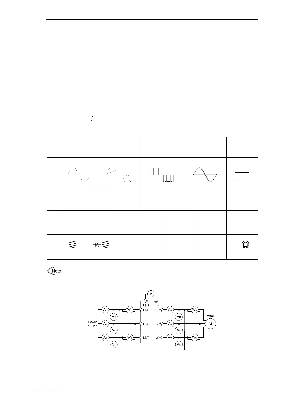
Table 7.4-1 Meters for Measurement of Main Circuit
Item
Input (primary) side Output (secondary) side
DC link
bus voltage
(P(+)-N(-))
Waveform
Voltage
Current
Voltage
Current
Name of
meter
Ammeter
AR, AS, AT
Voltmeter
VR, VS, VT
Wattmeter
WR, WT
Ammeter
AU, AV, AW
Voltmeter
VU, VV, VW
Wattmeter
WU, WW
DC voltmeter
V
Type of
meter
Moving
iron type
Rectifier or
moving iron
type
Digital AC
power meter
Digital AC
power meter
Digital AC
power meter
Digital AC
power meter
Moving coil type
Symbol of
meter
⎯ ⎯ ⎯ ⎯
It is not recommended that meters other than a digital AC power meter be used for measuring the output
voltage or output current since they may cause larger measurement errors or, in the worst case, they may
be damaged. For more precise measurement, a digital AC power meter is strongly recommended.
Figure 7.4-1 Connection of Meters

 Loading...


