5.4 Details of Function Codes
5-272
5.4.10 y codes (Link functions)
y01 to y20
RS-485 Setting 1, RS-485 Setting 2
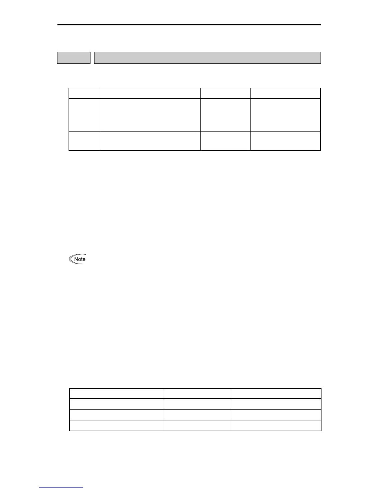
Up to two ports of RS-485 communications link are available.
Table 5.4-194
Ports Connection Method Function Code Applicable Equipment
Port 1
RS-485 communications link (port 1)
(via the RJ-45 connector prepared for
keypad connection)
y01 through y10
Standard keypad
Inverter support loader
Host equipment
(higher-level equipment)
Port 2
RS-485 communications link (port 2)
via terminal block (DX+, DX-, and SD)
y11 through y20
Host equipment
(higher-level equipment)
Outlines of each corresponding equipment are as follows.
(1) Standard keypad
The standard keypad allows you to run and monitor the inverter.
It can be used independent of the y code setting.
(2) Inverter support loader (FRENIC loader)
When the computer, of which FRENIC loader is installed, is connected via the RS-485 communication (port
1), inverter support (monitoring, function code editing, test running) is possible.
For the settings of y codes, see the descriptions of function codes y01 to y10.
FRENIC-MEGA series of inverters has a USB port on the keypad. When connecting to the inverte
support loader via the USB port, simply set "1" (factory default) to the station address (y01).
(3) Host equipment (higher-level equipment)
The inverter can be controlled and monitored by connecting host equipment such as a host equipment
(higher level equipment) such as the PLC and the controller. Modbus RTU
*
protocol and Fuji
general-purpose inverter protocol are available for communications protocols.
* Modbus RTU is a protocol established by Modicon, Inc.
See the RS-485 Communication User's Manual for details.
Station address (y01, y11)
Station addresses of the RS-485 communications link can be set. The setting range is different for each
protocol.
Table 5.4-195
Protocol Range Broadcast Address
Modbus RTU
1 to 247 0
Protocol for loader command
1 to 255 -
Fuji general-purpose inverter
1 to 31 99
- When the section outside of the range is specified, no response is returned.
- Match the setting, which is applied when the inverter support loader is used via RS-485 communication
(port 1), to the computer side setting.

 Loading...


