2.2 Wiring
2-35
Chapter 2 INSTALLATION AND WIRING
2.2.7 Setting up the slide switches
Before changing the switches, turn OFF the power and wait at least five minutes for inverters with a
capacity of 22 kW or below, or at least ten minutes for inverters with a capacity of 30 kW or above.
Make sure that the LED monitor and charging lamp are turned OFF. Further, make sure, using a
multimeter or a similar instrument, that the DC link bus voltage between the terminals P(+) and N(-) has
dropped to the safe level (+25 VDC or below).
Risk of electric shock exists.
Switching the slide switches
located on the control PCB allows you to customize the operation mode of the
analog output terminals, digital I/O terminals, and communications ports. The locations of these switches are
shown in Figure 2.2-30.
To access the slide switches, remove the front cover so that you can see the control PCB. For inverters with a
capacity of 30 kW or above,
open also the keypad enclosure.
For details on how to remove the front cover and how to open and close the keypad enclosure, refer to
Section 2.2.2 "Removing and mounting the front cover and the wiring guide."
Table 2.2-21 lists the function of each slide switch.
Table 2.2-21 Function of Each Slide Switch
Slide Switch Function
SW1
<Switches the service mode of the digital input terminals between SINK and
SOURCE>
- This switches the input mode of digital input terminals [X1] to [X9], [FWD] and
[REV] to be used as the SINK or SOURCE mode.
- Factory default:
SINK
SW2
<Switches
the terminating resistor of RS-485 communications port on the inverter ON
and OFF. (RS-485 communications port 2, on the control PCB)>
-
If the inverter is connected to the RS-485 communications network as a
terminating device, turn SW2 to ON.
SW3
<Switches the terminating resistor of RS-485 communications port on the inverter ON
and OFF. (RS-485 communications port 1, for connecting the keypad)>
-
To connect a keypad to the inverter, turn SW3 to OFF. (Factory default)
-
If the inverter is connected to the RS-485 communications network as a
terminating device, turn SW3 to ON.
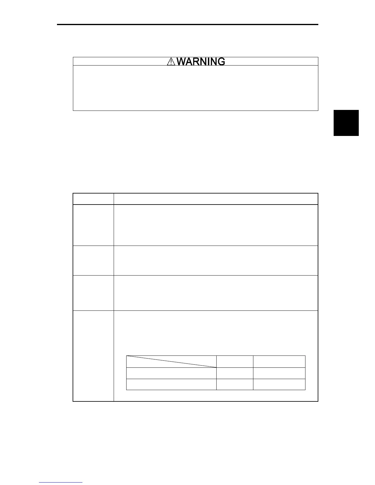
SW4
<Switches the output mode of the analog output terminal [FMA]
between voltage and
current.>
This switches the output form (VO/IO) of the terminal [FMA]. When changing this
switch setting, also change the data of function code F29.
Table 2.2-22
SW4 Set data of F29 to:
Voltage output (Factory default) VO 0
Current output IO 1
Output mode

 Loading...


