Measurement evaluation | Defining tolerances
11
Short description
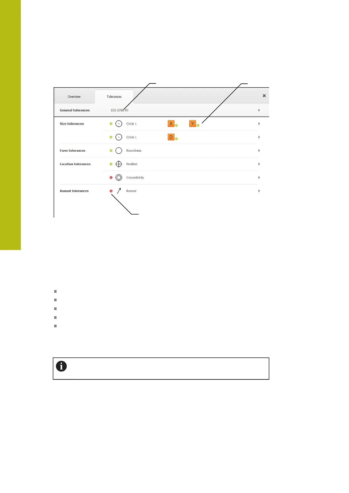
Figure 68: Details dialog with Tolerances tab
1
Display of general tolerance
2
List of tolerances, depending on feature
3
Status of the tolerance: Active and within the tolerance or active and outside
the tolerance
On the Tolerances tab, you can define the geometrical tolerancing of a measured
or constructed feature. The tolerances are grouped.
Depending on the feature, you can define the following tolerances:
Size tolerances (e.g., diameter, width, length, and angle of the reference axis)
Form tolerances (e.g., roundness)
Location tolerances (e.g., position, concentricity)
Directional tolerances (e.g., angularity, parallelism, perpendicularity)
Runout tolerances
The tolerances can be activated or deactivated for each feature. To define
tolerances for a feature, tolerance values can be entered manually, or standard
values can be taken over from general tolerances (e.g., the ISO 2768 standard).
Tolerances cannot be applied to reference features, such as zero point,
alignment, and reference plane.
282
HEIDENHAIN | QUADRA-CHEK 2000 | Operating Instructions | 07/2019
 Loading...