Installation | Connecting encoders
5.4 Connecting encoders
For encoders with an EnDat 2.2 interface: If the corresponding encoder
input has already been assigned to an axis in the device settings, then
the encoder is automatically detected upon restart, and the settings are
adapted. Alternatively, you can assign the encoder input after you have
connected the encoder.
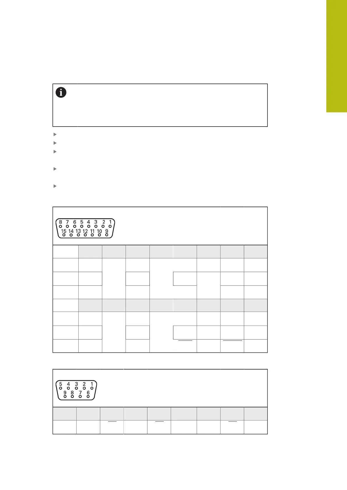
Comply with the pin layout
Remove and save the dust protection cap
Route the cables depending on the mounting variant
Further information: "Assembly of the product", Page 40
Connect the encoder cables tightly to the respective connections
Further information: "Device overview", Page 47
If the cable connectors include mounting screws, do not overtighten them
Pin layout of X1, X2, X3
1 V
PP
, 11 µA
PP
, EnDat 2.2
1 2 3 4 5 6 7 8
1 V
PP
A+ B+ / / R– /
11 μA
PP
I
1+
I
2+
/ I
0+
/
EnDat /
0 V
/
U
P
DATA
Inter-
nal
shield
/ CLOCK
9 10 11 12 13 14 15
1 V
PP
A– B- / R+ /
11 μA
PP
I
1-
I
2-
/ I
0+
/
EnDat /
Sense
0 V
/
Sense
U
P
DATA / CLOCK
Pin layout of X21, X22, X23
TTL
1 2 3 4 5 6 7 8 9
/ U
a1
U
a1
U
a2
U
a2
0 V U
p
U
a0
U
a0
5
HEIDENHAIN | QUADRA-CHEK 2000 | Operating Instructions | 07/2019
49
 Loading...