4-21
dummyheaddummyhead
PGM-FI SYSTEM
DTC TROUBLESHOOTING
DTC 1-1 (MAP SENSOR LOW
VOLTAGE)
• If the ECM/PCM is replaced, perform the following:
– Key Registration Procedure (page 23-6)
– Clutch Initialize Learning Procedure (NC700XD/
SD) (page 12-120)
1. MAP Sensor System Inspection
Turn the ignition switch ON and engine stop switch
"".
Check the MAP sensor with the HDS pocket tester.
Is about 0 V indicated?
YES – GO TO STEP 2.
NO – Intermittent failure
2. Sensor Unit Power Line Inspection
Check the sensor unit power line inspection (page
4-17).
Is the sensor unit power line normal?
YES – GO TO STEP 3.
NO – Replace or repair the abnormal circuit.
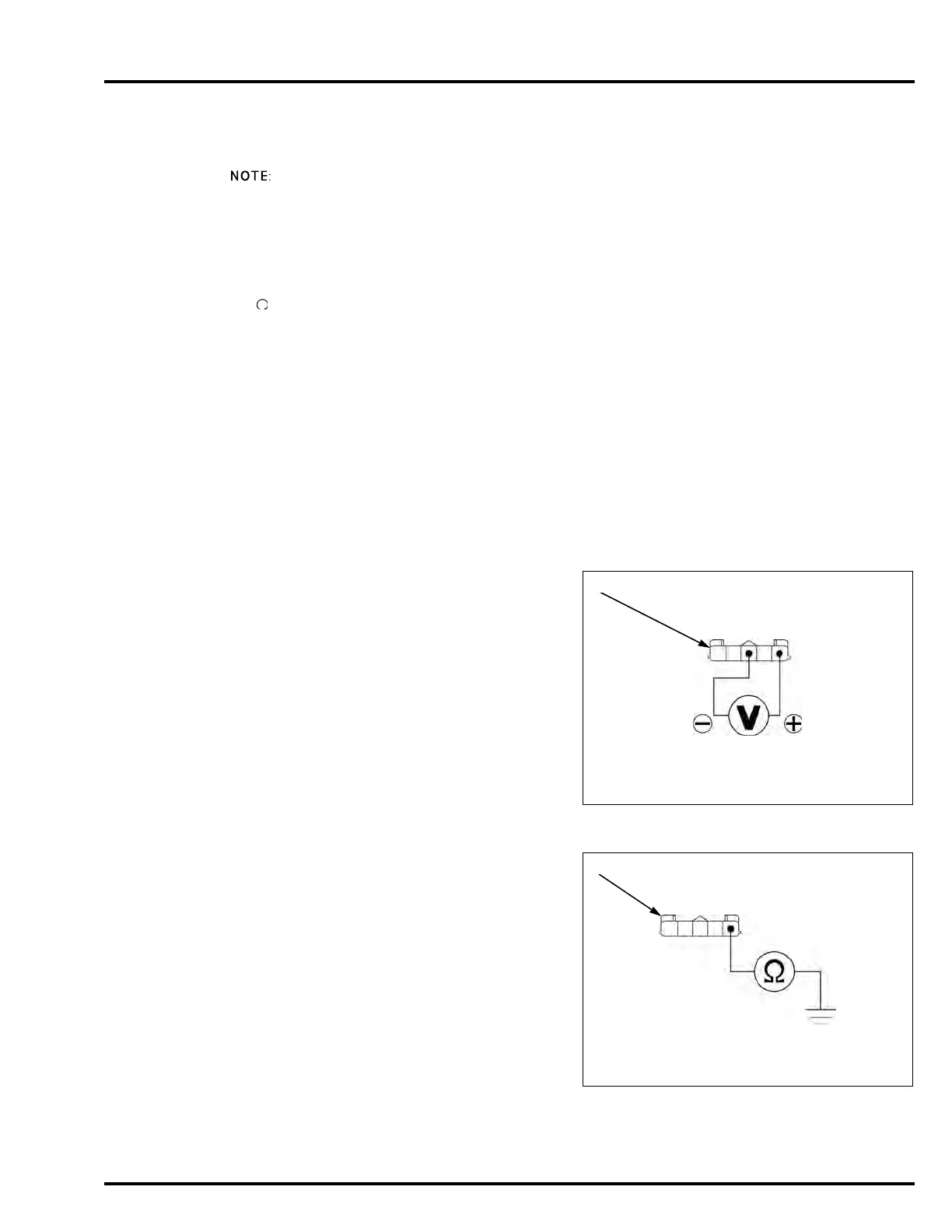
3. MAP Sensor Output Voltage Inspection
Turn the ignition switch OFF.
Disconnect the sensor unit 5P (Black) connector [1].
Turn the ignition switch ON.
Measure the voltage at the sensor unit 5P (Black)
connector of the wire harness side.
Is the voltage within 4.75 – 5.25 V?
YES – GO TO STEP 5.
NO – GO TO STEP 4.
4. MAP Sensor Output Line Short Circuit
Inspection
Turn the ignition switch OFF.
Check for continuity between the sensor unit 5P
(Black) connector [1] of the wire harness side and
ground.
Is there continuity?
YES – Short circuit in the Violet/red wire
NO – GO TO STEP 5.
Connection: Violet/red (+) – Green/yellow (–)
Standard: 4.75 – 5.25 V
Connection: Violet/red – ground

 Loading...