5-7
dummyheaddummyhead
IGNITION SYSTEM
Remove the shroud/side cover (NC700X/XA/XD) (page
2-14).
Remove the side cowl (NC700S/SA/SD) (page 2-13)
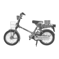
With the ignition coil primary wire connected, connect
the peak voltage adaptor or Imrie tester to the ignition
coil primary terminal [1] and ground.
Turn the ignition switch ON and engine stop switch " ".
Check the initial voltage at this time.
The battery voltage should be measured.
If the initial voltage cannot be measured, follow the
checks described in the troubleshooting table (page 5-
5).
Shift the transmission into neutral.
Crank the engine with the starter motor and measure
the ignition coil primary peak voltage.
If the peak voltage is abnormal, follow the checks
described in the troubleshooting table (page 5-5).
Install the shroud/side cover (NC700X/XA/XD) (page 2-
14).
Install the side cowl (NC700S/SA/SD) (page 2-13).
CKP SENSOR PEAK VOLTAGE
(NC700X/XA/S/SA)
Check the cylinder compression and check that the
spark plugs are installed correctly in the cylinder head.
Disconnect the ECM 33P (Black) connector [1] (page 4-
67).
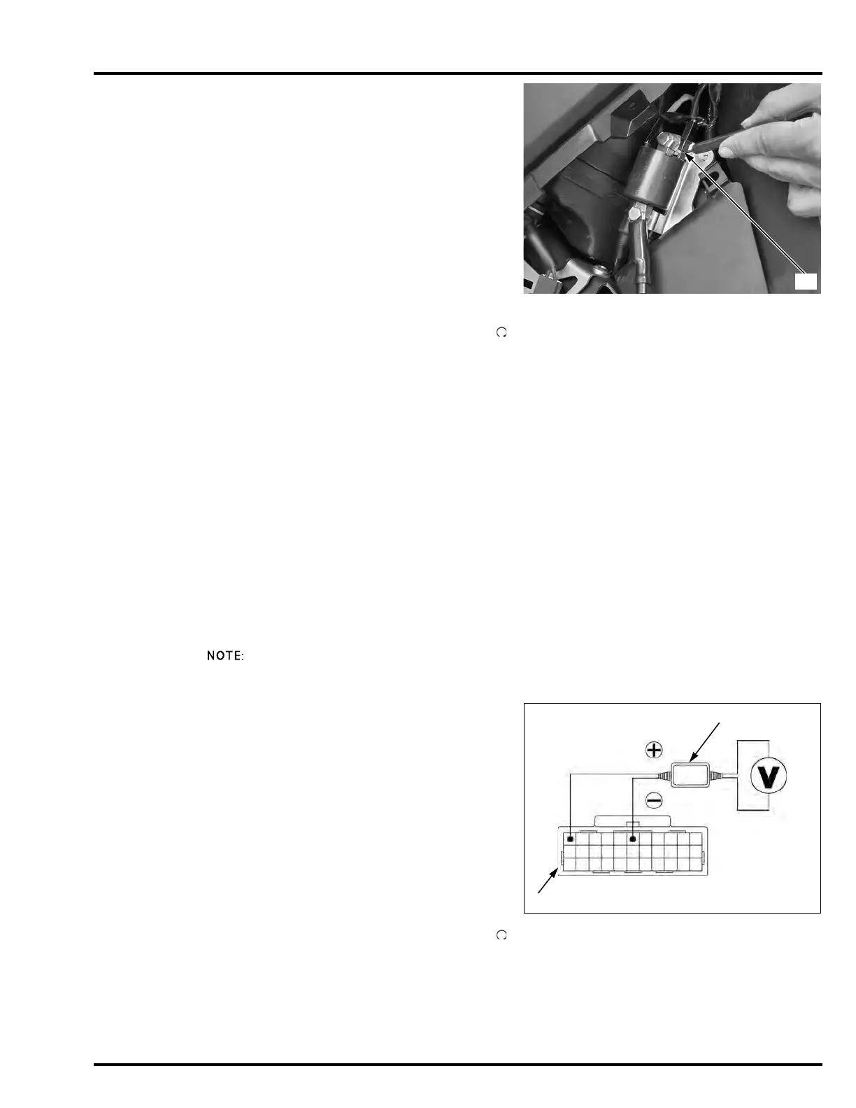
Connect the peak voltage tester or adaptor probes to
the ECM 33P (Black) connector terminals of the wire
harness side.
Shift the transmission into neutral.
Turn the ignition switch ON and engine stop switch " ".
Crank the engine with the starter motor and measure
the CKP sensor peak voltage.
If the peak voltage measured at the ECM 33P (Black)
connector is abnormal, measure the peak voltage at the
CKP sensor connector.
Do not disconnect
the ignition coil
primary wire.
TOOL:
Imrie diagnostic tester (model 625) or
Peak voltage adaptor 07HGJ-0020100
with commercially available digital multimeter
(impedance 10 M/DCV minimum)
CONNECTION:
No.1: Blue/yellow (+) – Ground (–)
No.2: Yellow/blue (+) – Ground (–)
Avoid touching the
spark plug and
tester probes to
prevent electric
shock.
PEAK VOLTAGE: 100 V minimum
TOOLS:
Imrie diagnostic tester (model 625) or
Peak voltage adaptor [2] 07HGJ-0020100
with commercially available digital multimeter
(impedance 10 M/DCV minimum)
Test probe 07ZAJ-RDJA110
CONNECTION: Yellow (+) – Green/orange (–)
PEAK VOLTAGE: 0.7 V minimum

 Loading...