12-94
dummyheaddummyhead
DUAL CLUTCH TRANSMISSION (DCT) (NC700XD/SD)
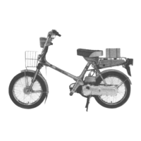
2. Shift Pedal Angle Sensor Input Voltage
Inspection
Turn the ignition switch OFF.
Disconnect the shift pedal angle sensor 3P (Black)
connector [1].
Turn the ignition switch ON and engine stop switch
"".
Measure the voltage between the wire harness side
shift pedal angle sensor 3P (Black) connector
terminals.
Is the voltage within 4.75 – 5.25 V?
YES – GO TO STEP 4.
NO – GO TO STEP 3.
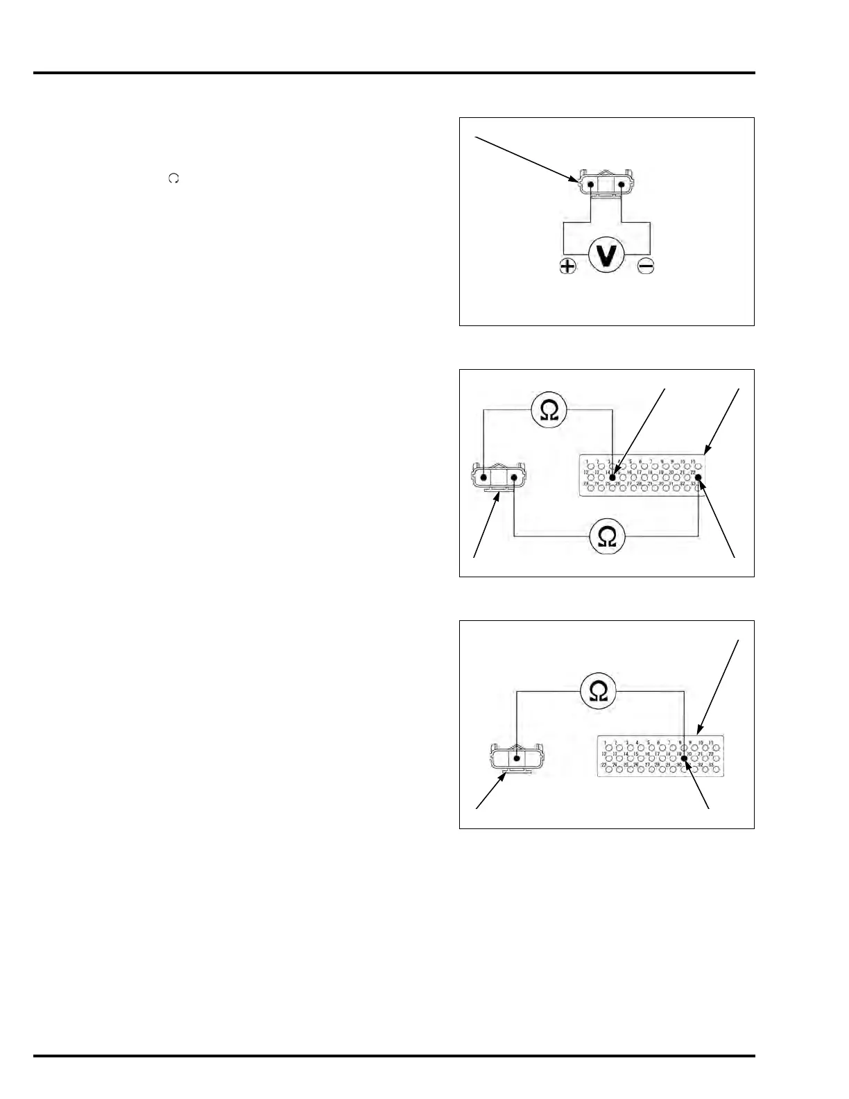
3. Shift Pedal Angle Sensor Open Circuit
Inspection
Turn the ignition switch OFF.
Connect the ECM test harness to the PCM
connectors (page 4-14).
Check for continuity between the shift pedal angle
sensor 3P (Black) connector [1] and test harness [2]
terminals.
Is there continuity?
YES – Replace the PCM with a known good one,
and recheck.
NO – • Open circuit in Green/yellow wire
• Open circuit in Yellow/red wire
4. Shift Pedal Angle Sensor Output Line Open
Circuit Inspection
Turn the ignition switch OFF.
Connect the ECM test harness to the PCM
connectors (page 4-14).
Check for continuity between the shift pedal angle
sensor 3P (Black) connector [1] and test harness [2]
terminals.
Is there continuity?
YES – GO TO STEP 5.
NO – Open circuit in Yellow/violet wire
Connection: Yellow/red (+) – Green/yellow (–)
Connection: Green/yellow – B22
Yellow/red – B14
Connection: Yellow/violet – B19

 Loading...