10-21
dummyheaddummyhead
CYLINDER HEAD/VALVES
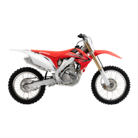
Measure and record each valve guide I.D.
Subtract each valve stem O.D. from the corresponding
guide I.D. to obtain the stem-to-guide clearance.
If the stem-to-guide clearance is out of standard,
determine if a new guide with standard dimensions
would bring the clearance within tolerance. If so,
replace any guides as necessary and ream to fit.
If the stem-to-guide clearance exceeds the service limit
with the new guides, replace the valves and guides.
VALVE GUIDE REPLACEMENT
Chill the replacement valve guides in the freezer
section of a refrigerator for about an hour.
Heat the cylinder head to 100 – 150°C (212 – 302°F)
with a hot plate or oven.
To avoid burns, wear heavy gloves when handling the
heated cylinder head.
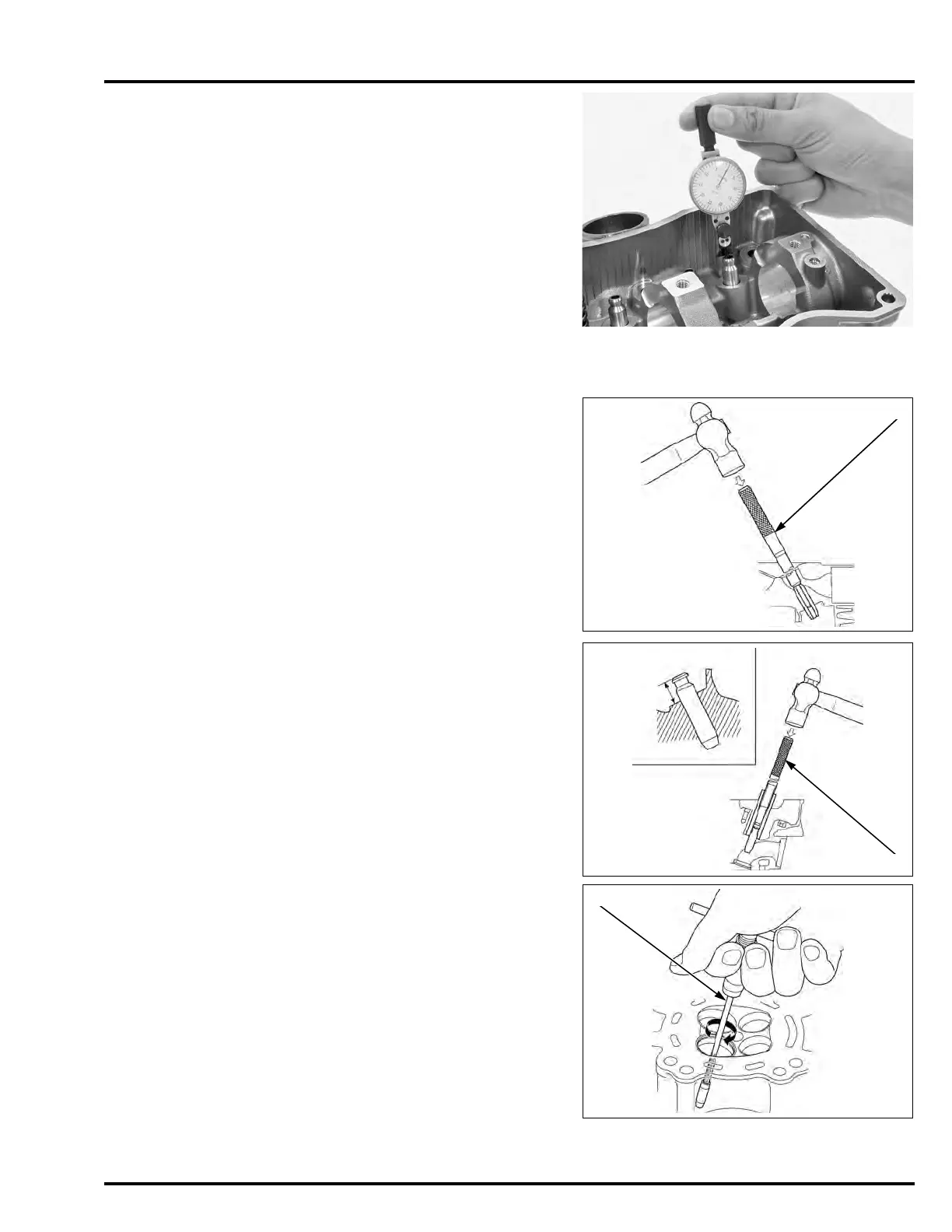
Support the cylinder head and drive out the valve
guides from combustion chamber side of the cylinder
head.
Drive in the valve guides to the specified depth from the
top of the cylinder head.
Let the cylinder head cool to room temperature.
Use cutting oil on
the reamer during
this operation.
Ream new valve guides after installation.
Insert the reamer [1] from the combustion chamber side
of the cylinder head and always rotate the reamer
clockwise.
Clean the cylinder head thoroughly to remove any
metal particles.
Reface the valve seat (page 10-22).
SERVICE LIMIT: 5.04 mm (0.198 in)
SERVICE LIMITS:
IN: 0.075 mm (0.0030 in)
EX: 0.085 mm (0.0033 in)
Reface the valve
seats whenever the
valve guides are
replaced (page 10-
22).
Do not use a torch
to heat the cylinder
head; it may cause
warping.
TOOL:
Valve guide driver [1] 07942-8920000
SPECIFIED DEPTH:
IN: 17.7 – 18.0 mm (0.70 – 0.71 in)
EX: 19.6 – 19.9 mm (0.77 – 0.78 in)
TOOL:
Valve guide driver [1] 07743-0020000
TOOL:
Valve guide reamer, 5.010 mm 07984-MA60001

 Loading...