12-77
dummyheaddummyhead
DUAL CLUTCH TRANSMISSION (DCT) (NC700XD/SD)
DTC 51 (TR SENSOR)
• Before starting the inspection, check for loose or
poor contact on the TR sensor 3P (Black) and PCM
33P connectors and recheck the DTC.
• If the PCM is replaced, perform the following:
– Key Registration Procedure (page 23-6)
– Clutch Initialize Learning Procedure (page 12-120)
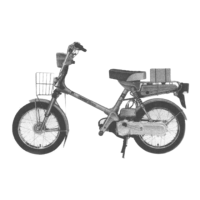
1. TR Sensor Input Voltage Inspection
Turn the ignition switch OFF.
Disconnect the TR sensor 3P (Black) connector.
Turn the ignition switch ON with the engine stop
switch " ".
Measure the voltage between the wire harness side
TR sensor 3P (Black) connector [1] terminals.
Is the voltage within 4.75 – 5.25 V?
YES – GO TO STEP 2.
NO – GO TO STEP 5.
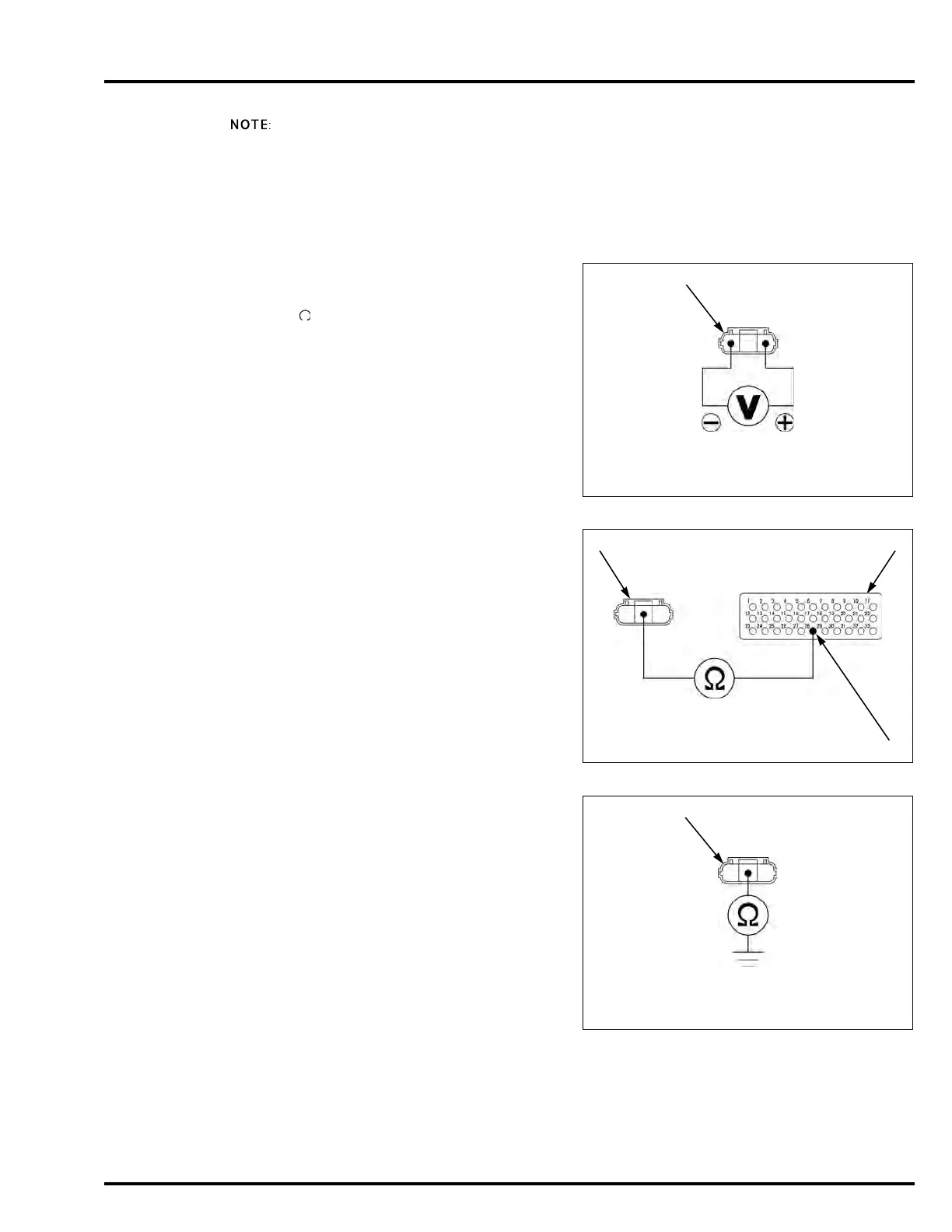
2. TR Sensor Output Line Open Circuit Inspection
Connect the ECM test harness to the PCM
connectors (page 4-14).
Check for continuity between the wire harness side
TR sensor 3P (Black) connector [1] and test
harness [2] terminals
Is there continuity?
YES – GO TO STEP 3.
NO – Open circuit in the Black/pink wire
3. TR Sensor Output Line Short Circuit Inspection
Check for continuity between the wire harness side
TR sensor 3P (Black) connector [1] terminal and
ground.
Is there continuity?
YES – Short circuit in the Black/pink wire
NO – GO TO STEP 4.
Connection: Yellow/red (+) – Green/yellow (–)
Connection: Black/pink – A28
Connection: Black/pink – Ground

 Loading...