22-13
dummyheaddummyhead
LIGHTS/METERS/SWITCHES
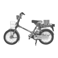
Check for continuity between the combination meter
16P (Gray) connector [1] of the wire harness side
and ground.
Is there continuity?
YES – Short circuit in Red/blue wire
NO – GO TO STEP 2.
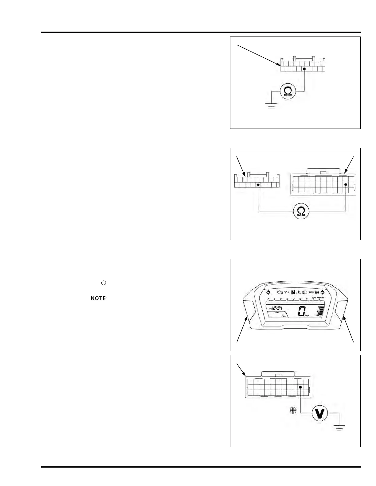
2. Combination Meter Serial Line Open Circuit
Inspection
Check for continuity between the combination meter
16P (Gray) connector [1] and ECM/PCM 33P
connector [2] of the wire harness side.
Is there continuity?
YES – GO TO STEP 3.
NO – Open circuit in Red/blue wire
3. Combination Meter Serial Line Output Voltage
Inspection
Connect the combination meter 16P (Gray)
connector.
Turn the ignition switch ON and engine stop switch
" " while pushing and holding combination meter A
button [1] and B button [2] over 10 seconds.
The combination meter enters the communication
diagnostic mode.
Measure the voltage at the ECM/PCM 33P
connector [1] of the wire harness side and ground.
Does the standard voltage exist?
YES – GO TO STEP 4.
NO – • Replace the combination meter
assembly.
– NC700X/XA/XD (page 22-9)
– NC700S/SA/SD (page 22-9)
Connection: Red/blue – Ground
Connection: Red/blue – Red/blue
TOOL:
Test probe 07ZAJ-RDJA110
Connection: Red/blue (+) – Ground (–)
Standard: 8 V or more (Every 5 seconds)
TOOL:
Test probe 07ZAJ-RDJA110

 Loading...