4-48
dummyheaddummyhead
PGM-FI SYSTEM
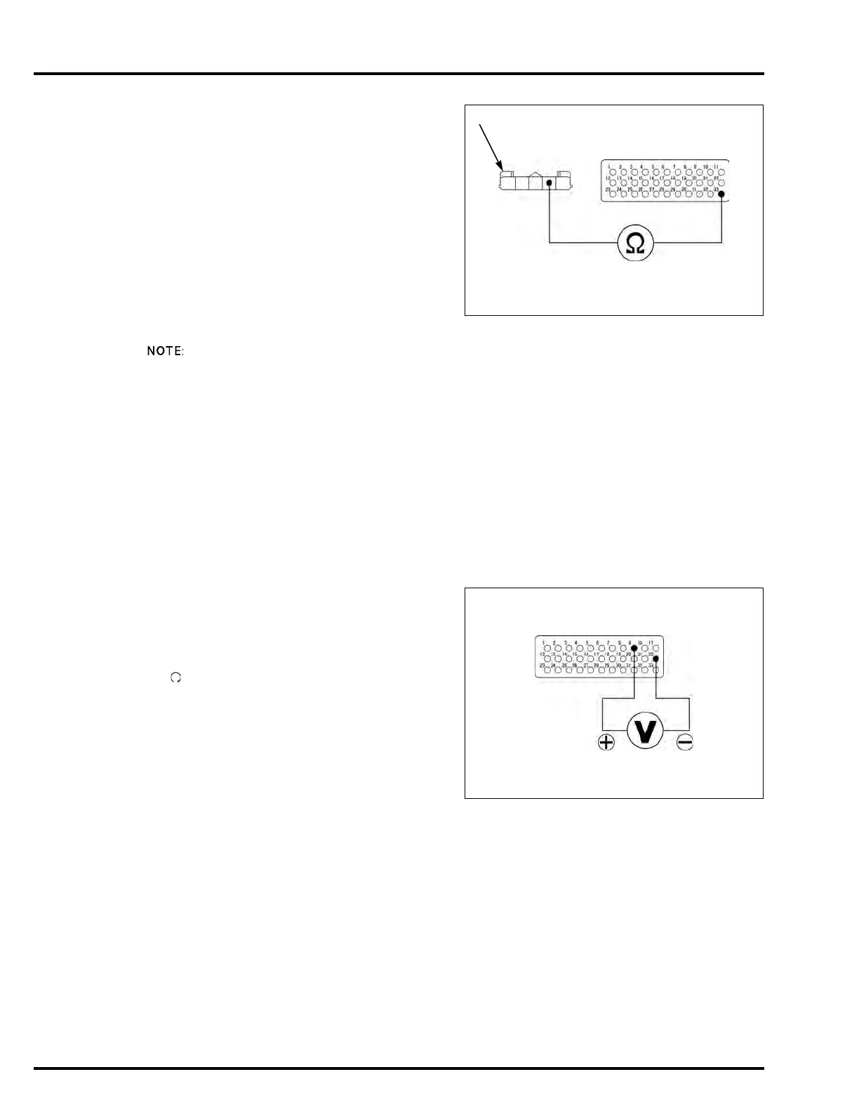
4. TP Sensor Output Line Open Circuit Inspection
Check for continuity between the sensor unit 5P
(Black) connector [1] of the wire harness side and
ECM test harness.
Is there continuity?
YES – Faulty sensor unit (TP sensor)
NO – Open circuit in the Red/yellow wire
MIL 9 BLINKS (IAT SENSOR)
• NC700X/XA/S/SA:
Before starting the inspection, check for loose or
poor contact on the IAT sensor 2P (Black) connector
and ECM 33P (Black) connector, then recheck the
MIL blinking.
• NC700XD/SD:
Before starting the inspection, check for loose or
poor contact on the IAT sensor 2P (Black) connector
and PCM 33P (Gray) connector, then recheck the
MIL blinking.
• If the ECM/PCM is replaced, perform the following:
– Key Registration Procedure (page 23-6)
– Clutch Initialize Learning Procedure (NC700XD/
SD) (page 12-120)
1. IAT Sensor Output Voltage Inspection
Connect the ECM test harness to the ECM/PCM
33P connector(s).
– NC700X/XA/S/SA (page 4-13)
– NC700XD/SD (page 4-14)
Turn the ignition switch ON and engine stop switch
"".
Measure the voltage at the ECM test harness
terminals.
Is the voltage within 2.7 – 3.1 V (20°C/68°F)?
YES – Intermittent failure
NO – GO TO STEP 2.
Connection:
NC700X/XA/S/SA:
33 – Red/yellow
NC700XD/SD:
B33 – Red/yellow
Connection:
NC700X/XA/S/SA:
9 (+) – 22 (–)
NC700XD/SD:
B9 (+) – B22 (–)
Standard: 2.7 – 3.1 V (20°C/68°F)

 Loading...