4-49
dummyheaddummyhead
PGM-FI SYSTEM
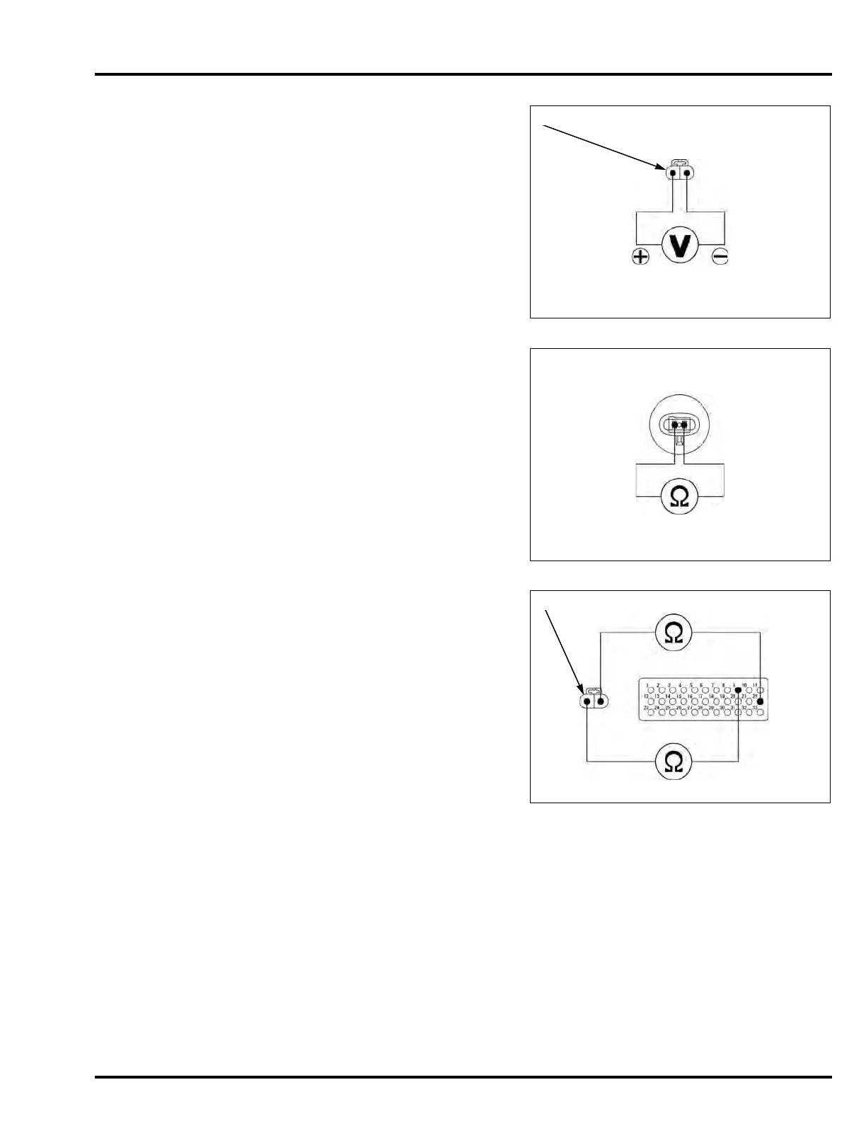
2. IAT Sensor Input Voltage Inspection
Turn the ignition switch OFF.
Disconnect the IAT sensor 2P (Black) connector [1].
Turn the ignition switch ON.
Measure the voltage at the IAT sensor 2P (Black)
connector of the wire harness side.
Is the voltage within 4.75 – 5.25 V?
YES – GO TO STEP 3.
NO – GO TO STEP 4.
3. IAT Sensor Resistance Inspection
Turn the ignition switch OFF.
Measure the resistance at the IAT sensor terminals.
Is the resistance within 2.2 – 2.7 k (20°C/68°F)?
YES – Replace the ECM/PCM with a known good
one, and recheck.
NO – Faulty IAT sensor
4. IAT Sensor Line Open Circuit Inspection
Turn the ignition switch OFF.
Check for continuity between the IAT sensor 2P
(Black) connector [1] of the wire harness side and
ECM test harness.
Is there continuity?
YES – GO TO STEP 5.
NO – • Open circuit in the Gray/blue wire
• Open circuit in the Green/yellow wire
Connection: Gray/blue (+) – Green/yellow (–)
Standard: 4.75 – 5.25 V
Standard: 2.2 – 2.7 k (20°C/68°F)
Connection:
NC700X/XA/S/SA:
9 – Gray/blue
22 – Green/yellow
NC700XD/SD:
B9 – Gray/blue
B22 – Green/yellow
Gr/Bu
[1]
G/Y 22 or B22
9 or B9

 Loading...