213
• All devices on the network are in the same MST region.
• Packets of VLAN 10, VLAN 20, VLAN 30, and VLAN 40 are forwarded along MSTI 1, MSTI 2,
MSTI 3, and MSTI 0, respectively.
• Switch A and Switch B operate at the distribution layer; Switch C and Switch D operate at the
access layer. VLAN 10 and VLAN 20 are terminated on the distribution layer devices, and VLAN
30 is terminated on the access layer devices, so the root bridges of MSTI 1 and MSTI 2 are Switch
A and Switch B, respectively, and the root bridge of MSTI 3 is Switch C.
Figure 189 Network diagram
NOTE:
"Permit:" next to a link in the fi
ure is followed by the VLANs the packets of which are permitted to pass
this link.
Configuration procedure
Configuring Switch A
1. Configure an MST region:
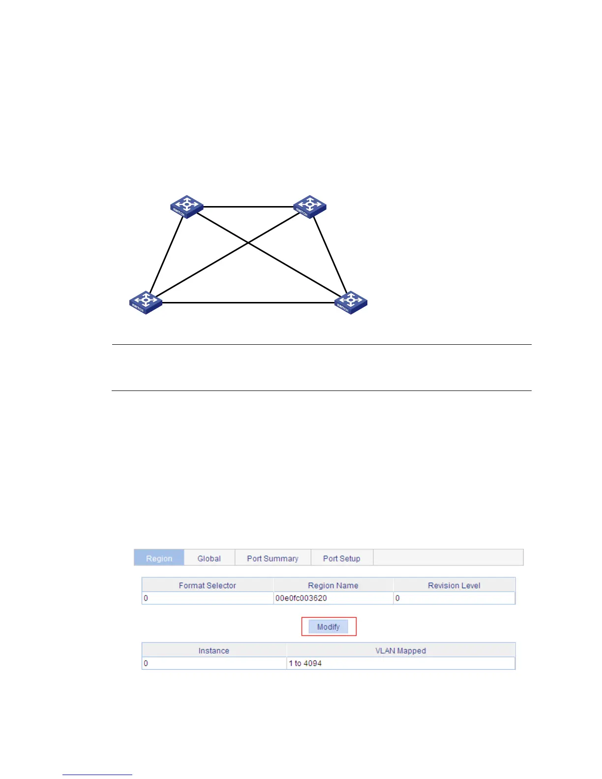
a. From the navigation tree, select Network > MSTP.
By default, the Region tab is displayed.
b. Click Modify.
Figure 190 The region tab
c. Set the region name to example.
d. Set the revision level to 0.
Permit: all VLAN
Permit:
VLAN 20, 40
Permit:
VLAN 10, 40
Permit: VLAN 30, 40
Permit:
VLAN 20, 40
Permit:
VLAN 10, 40
Switch A Switch B
Switch C Switch D

 Loading...