251
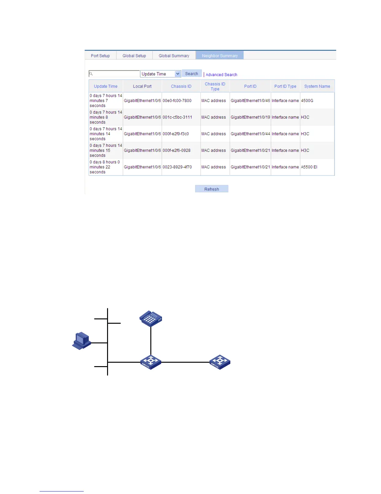
Figure 213 The Neighbor Summary tab
LLDP configuration examples
LLDP basic settings configuration example
Network requirements
As shown in Figure 214, configure LLDP on Switch A and Switch B so that the network management
station (NMS) can determine the status of the link between Switch A and MED and the link between
Switch A and Switch B.
Figure 214 Network diagram
Configuring Switch A
1. Enable LLDP on GigabitEthernet 1/0/1 and GigabitEthernet 1/0/2. (Optional. By default, LLDP is
enabled on Ethernet ports.)
2. Set the LLDP operating mode to Rx on GigabitEthernet 1/0/1 and GigabitEthernet 1/0/2:
a. Select Network > LLDP from the navigation tree.
By default, the Port Setup tab is displayed.
NMS
Switch A
MED
Switch B
GE1/0/2
GE1/0/1
GE1/0/1
 Loading...