2H0/2HZ
2-2-1
2-2 Electrical Parts Layout
2-2-1 Electrical parts layout
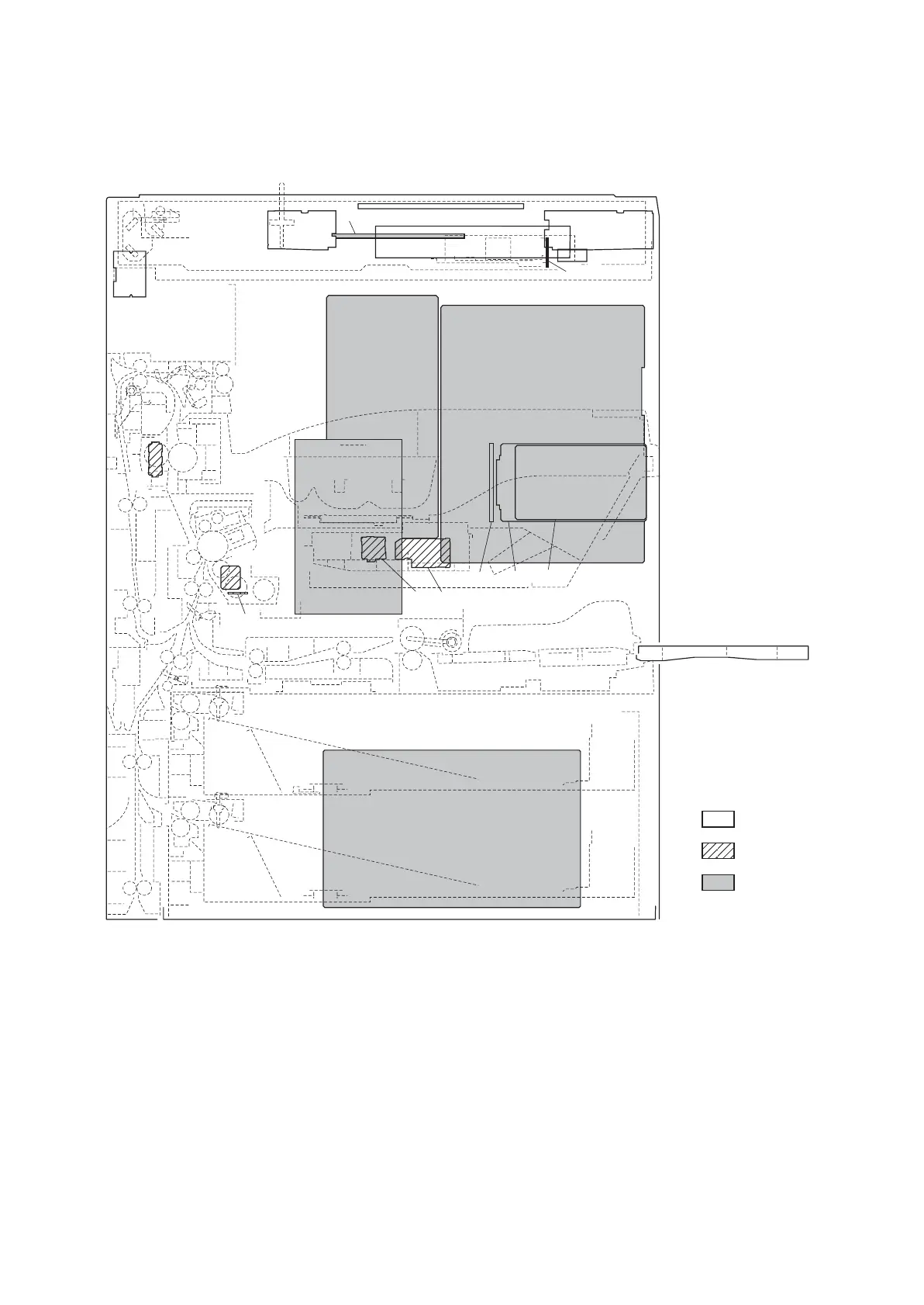
(1) PWBs
Figure 2-2-1 PWBs
1. Engine PWB (EPWB)................................... Controls the other PWBs, electrical components and optional devices.
2. Main PWB (MPWB) ..................................... Controls the image processing and operation panel.
3. Power source PWB (PSPWB) ..................... Generates +24 V DC and 5 V DC; controls the fuser heaters.
4. High voltage PWB (HVTPWB) ..................... Main charging. Generates developing bias and high voltages for transfer.
5. Scanner inverter PWB (SINPWB)................ Controls the exposure lamp.
6. LCD inverter PWB (LINPWB) ...................... Controls LCD indication.
7. CCD PWB (CCDPWB)................................. Reads the image of originals.
8. Main operation unit PWB (OPWB-M)........... Controls touch panel and LCD indication.
9. Right operation unit PWB (OPWB-R) .......... Consists of the operation keys and display LEDs.
10. Left operation unit PWB (OPWB-L) ............. Consists of the operation keys and display LEDs.
11. Upper operation unit PWB (OPWB-U) ......... Consists of the operation keys and display LEDs.
12. Front operation unit PWB (OPWB-F)........... Consists of the display LEDs.
Machine front
Machine inside
Machine rear
1
5
10
11
12
6
9
7
8
4
17
18
16
13
15 19 20
14
2
3
 Loading...