M800S/M80/E80 Series Connection and Setup Manual
6 Precautions for Connecting
225
IB-1501269-J
6.2 Turning the Power ON/OFF
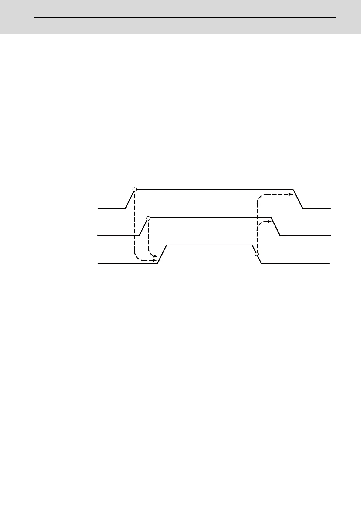
The diagram below shows the ON/OFF timing of the drive unit power supply (200VAC/400VAC), remote I/O unit power
supply (24VDC) and control unit power supply (24VDC).
[Power ON]
Turn the power ON in the following order; drive unit, remote I/O unit -> control unit
If the control unit is powered ON before the drive unit or remote I/O unit, the initial communication with the drive unit
or remote I/O unit may fail and the alarm "Servo communication error" or "Remote I/O unequipped error" may occur.
[Power OFF]
Turn the power OFF in the following order; control unit -> Remote I/O unit, drive unit.
If the remote I/O unit or drive unit is powered OFF before the control unit, the alarm "Remote I/O communication
error" may be occurred with the detection of remote I/O unit communication stop, or the alarms "Absolute value data
illegal", "Servo communication error", etc., may be occurred by the failure of data acquisition.
24VDC
(The remote I/O unit power)
24VDC
(The control unit power)
200VAC/(400VAC)
(The drive unit power)

 Loading...


