M800S/M80/E80 Series Connection and Setup Manual
7 Connection of Control Unit
240
IB-1501269-J
7.6.2 Connecting with Drive Unit MDS-EM/EMH Series
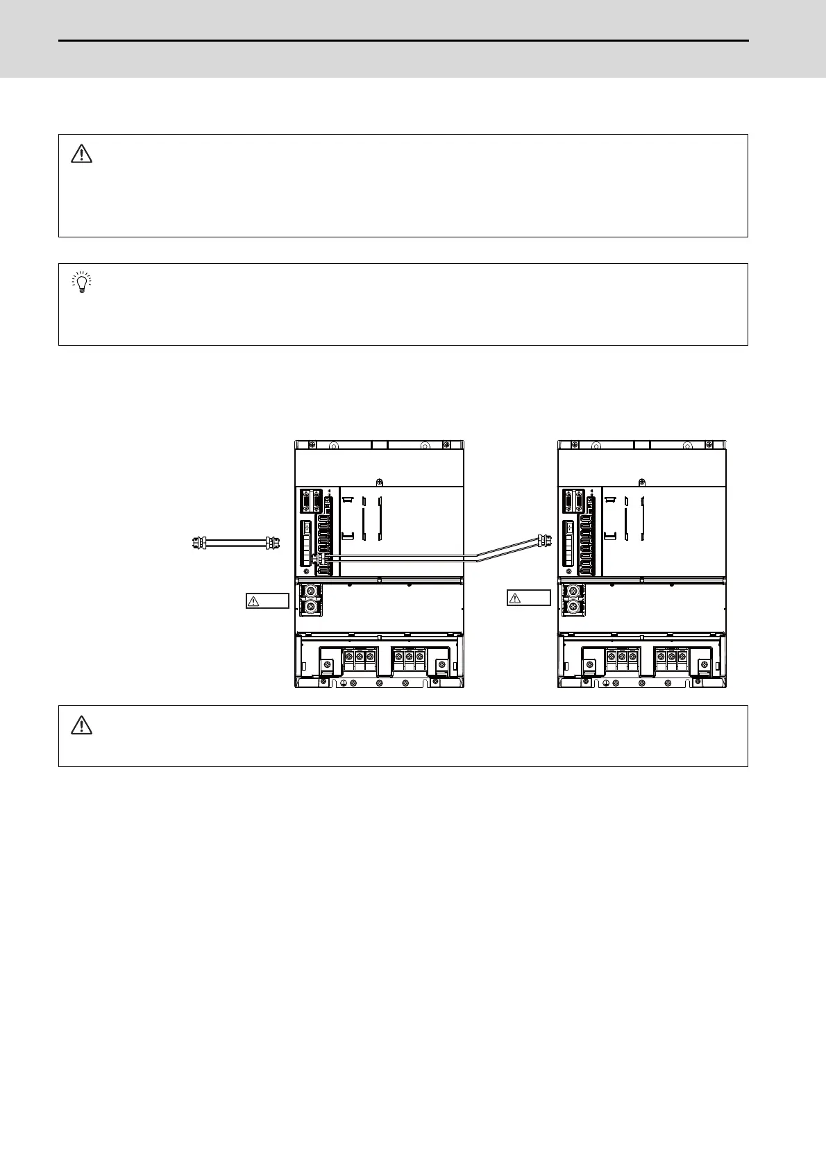
(1) When using only MDS-EM/EMH-SPV Series
CAUTION
Connect the NC and the drive units by the optical communication cables. The distance between the NC and the
final drive unit must be within 30m and the specified bending radius (for wiring inside panel: 25mm, and for wiring
outside panel: 50mm) or more.
POINT
Axis Nos. are determined by the rotary switch for setting the axis No. (Refer to the manual of drive unit.) The axis
No. has no relation to the order for connecting to the NC.
CAUTION
Confirm that the TE2 (L+, L-) wiring is not connected to other power supply before turning the power ON.
MDS-EM/EMH-SPV3
MDS-EM/EMH-SPV3
Spindle:1st axis
Servo:2nd/3rd/4th axis
to the NC
Connected
communication
Optical
cable
Refer to the
instruction
manual of each
NC for details.
Spindle:5th axis
Servo:6th/7th/8th axis
CAUTION
CAUTION

 Loading...


