M800S/M80/E80 Series Connection and Setup Manual
21 Confirming the Basic Operation
453
IB-1501269-J
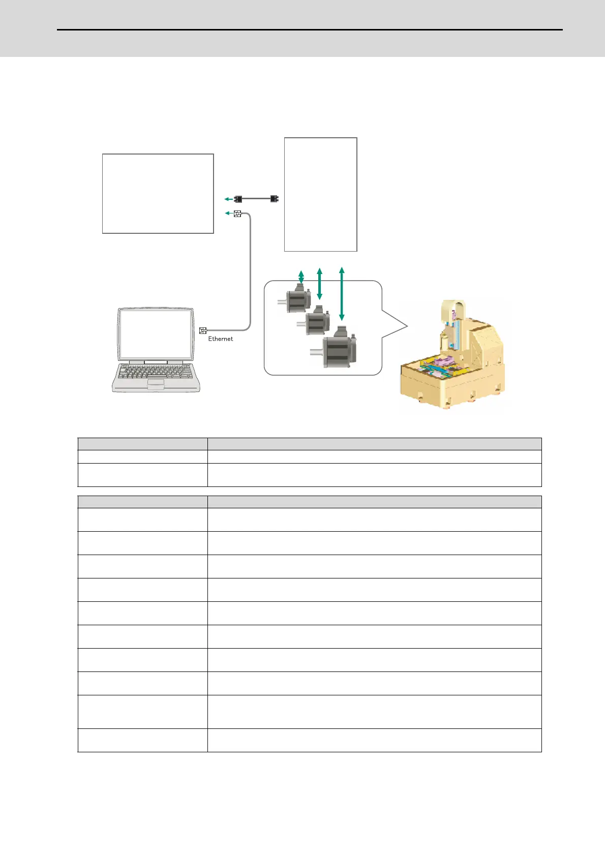
21.3.2 NC Analyzer2
Servo parameters can be automatically adjusted by measuring and analyzing the machine characteristics.
Measurement and analysis are conducted by driving the motor using machining programs for adjustment or vibration
signals. Various data can also be sampled.
<Functions>
(*1) For the measurement, create a program by the program creation function or use an arbitrary machining program.
(*2) Two or more NC axes in the same system are needed.
For details, refer to "NC Analyzer2 Instruction Manual" (IB-1501501326).
Adjustment wizard Description
Velocity loop gain adjustment Automatically adjusts velocity loop gain and resonance filters.
Lost motion adjustment Adjusts the lost motion automatically for the delay in responsecaused when the direction of
the machine rotates is reversed.
Measurement and adjustment Description
Frequency response measurement Measures the frequency response of speed loop for the designated axis. The result will be
output as frequency response waveform.
Reciprocation acceleration/
deceleration measurement
Measures the reciprocation acceleration/deceleration for the designated axis. The result will
be output as time-series waveform. (*1)
Roundness measurement Measures the roundness for the designated axis. The result will be output as roundness
waveform. (*1)
Synch tap error measurement Measures the synchronous tap error for the designated axis. The result will be output as time-
series waveform.(*1)
Spindle acceleration/deceleration
measurement
Measures the spindle acceleration/deceleration for the designated axis. The result will be
output as time-series waveform. (*1)
Spindle orientation measurement Measures the spindle orientation for the designated axis. The result will be output as time-
series waveform.(*1)
Spindle C-axis measurement Executes the reciprocation acceleration/deceleration measurement of spindle C axis with
specified axis. The result will be output as time-series waveform. (*1)
Spindle synchronization
measurement
Executes an arbitrary machining program with specified axis, and measures spindle
synchronization by using that data. The result will be output as time-series waveform.
PLC axis acceleration/deceleration
measurement
Executes an arbitrary machining program with specified axis, and measures PLC axis
acceleration/deceleration by using that data. The result will be output as time-series
waveform.
Arbitrary path measurement
(*2)
Executes an arbitrary machining program with specified two axes. The result will be output as
arbitrary path measurement waveform. (*1)
NC Analyzer2
Drive unit
Control unit

 Loading...


