M800S/M80/E80 Series Connection and Setup Manual
7 Connection of Control Unit
239
IB-1501269-J
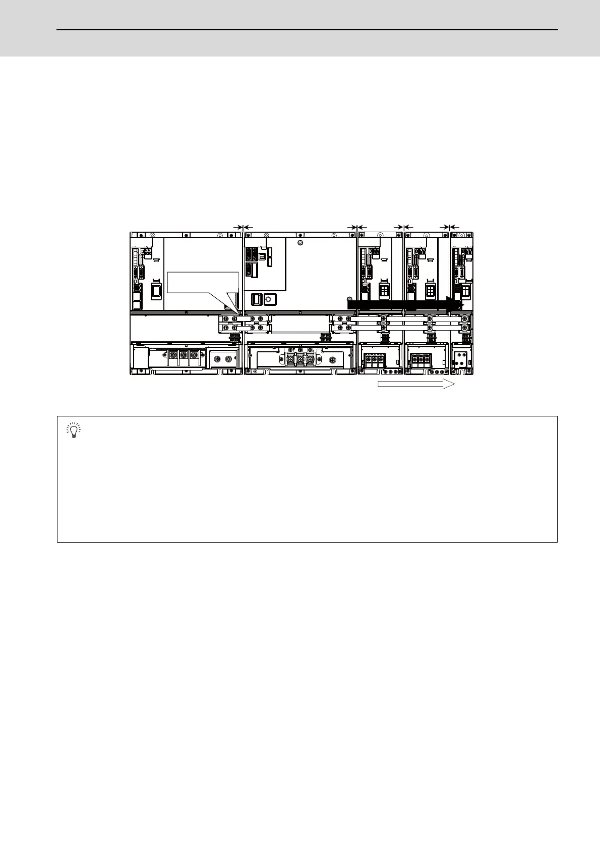
7.6.1.2 Drive Unit Arrangement
Arrange the drive units in the following procedure.
(1) Install a power supply unit.
(2) Arrange drive units in order of the nominal current from largest from the right.
(3) In the arrangement, the clearance between the units is 1 mm.
(4) Arrange the drive units with the DC connection length from the power supply unit being 1500mm or less.
For the arrangement of 1500mm or more, multiple power supply units are required.
(5) Arrange large capacity drive units at the left of the power supply unit with the clearance between the drive units
being 1mm.
POINT
1. Arrange large capacity drive units at the left of the power supply unit with the clearance between the drive units
being 1mm.
2. Power supply units equivalent to the number of large capacity drive units are required.
3. When arranging the drive unit at the right of the large capacity power supply unit, remove the side protection
cover of the power supply unit.
4. MDS-E-SP-400/640, MDS-EH-SP-200/320/480/600, and MDS-EH-V1-200 are the large capacity drive units.
1mm1mm
1mm
1mm
Large
Small
Arrange drive units in order of nominal current from largest.
Use the dedicated
connection bar.
1500mm or less

 Loading...


