M800S/M80/E80 Series Connection and Setup Manual
7 Connection of Control Unit
228
IB-1501269-J
The method for connecting to each unit and device from the control unit is explained in this chapter.
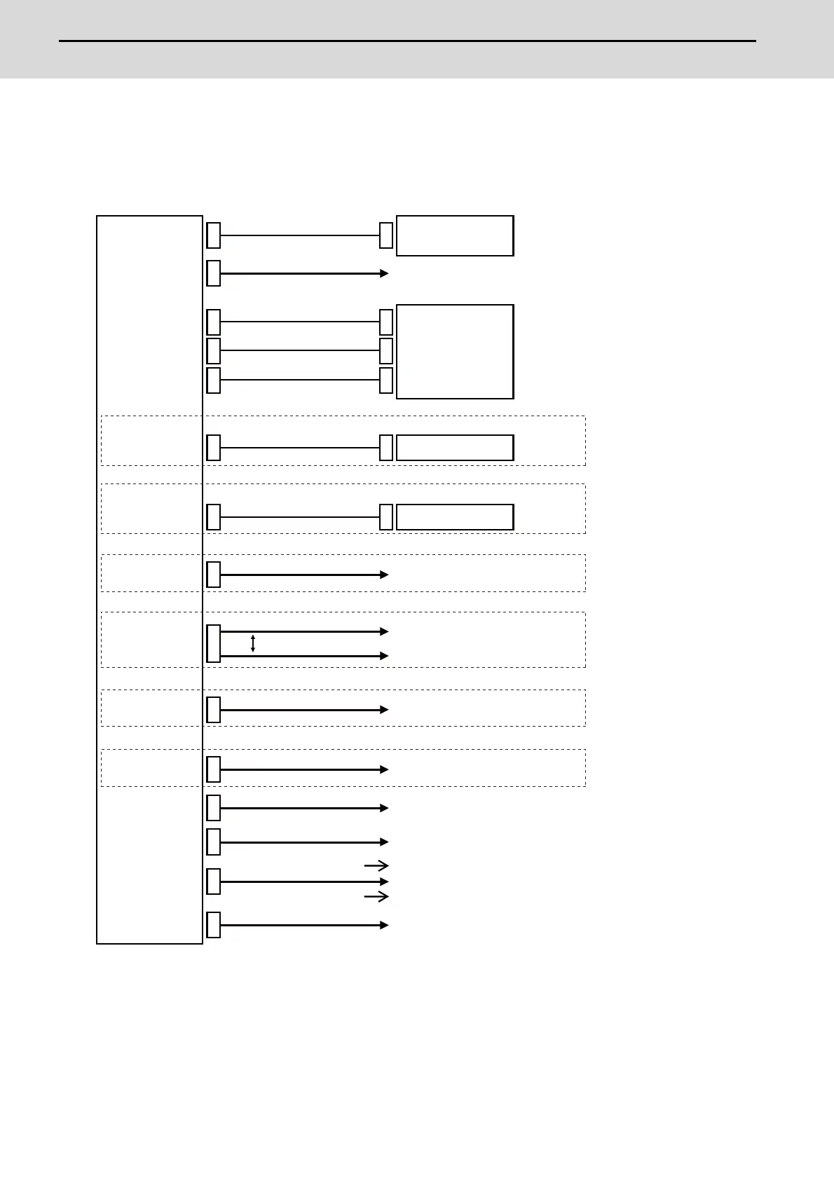
7.1 Control Unit Connection System Drawing
(Note 1) The mounted connector differs depending on the unit. Refer to the following chapter for which of the connector
is mounted.
"General specifications: Control Unit [M800S]"
"General specifications: Control Unit [M80]"
"General specifications: Control Unit [E80]"
(Note 2) For the connection of MITSUBISHI CNC machine operation panel, refer to the chapter "Connection of
MITSUBISHI CNC Machine Operation Panel".
LCD
SIO
ENC
SKIP
OPTH1/OPTH2
RIO1/RIO2
CJ71
EMG
DCIN
J026/J027
J100
J210
R050/R054
J395/J396/G380
J030/J031
J070/J071
CJ71
J010
LAN1/LAN2
J303
J120
BL
MENUKEY
OPTH1
J395/J396/G380
CJ71 RIO3
J012
[FCU8-DX731/DX750/DX760/DX761]
RIO1/RIO2
J210
[FCU8-DX834]
cable
Network
Control unit
Display unit
RS-232C device
Synchronous feed encoder, or
cable
Skip input (Sensor input)
cable
Remote I/O unit
cable
cable
cable
5V manual pulse generator
Servo/Spindle drive unit
cable
cable
Operation panel I/O unit
cable
Emergency stop signal
cable
Attached cable of unit
Attached cable of unit
Attached cable of unit
Servo/Spindle drive unit
cable
For M800S
For M80/E80
24VDC Stabilized
power supply
cable
Operation panel I/O unit
For M800S/M80
Remote I/O unit
cable
For E80
Pulse-controlled inverter
Select

 Loading...


