M800S/M80/E80 Series Connection and Setup Manual
7 Connection of Control Unit
241
IB-1501269-J
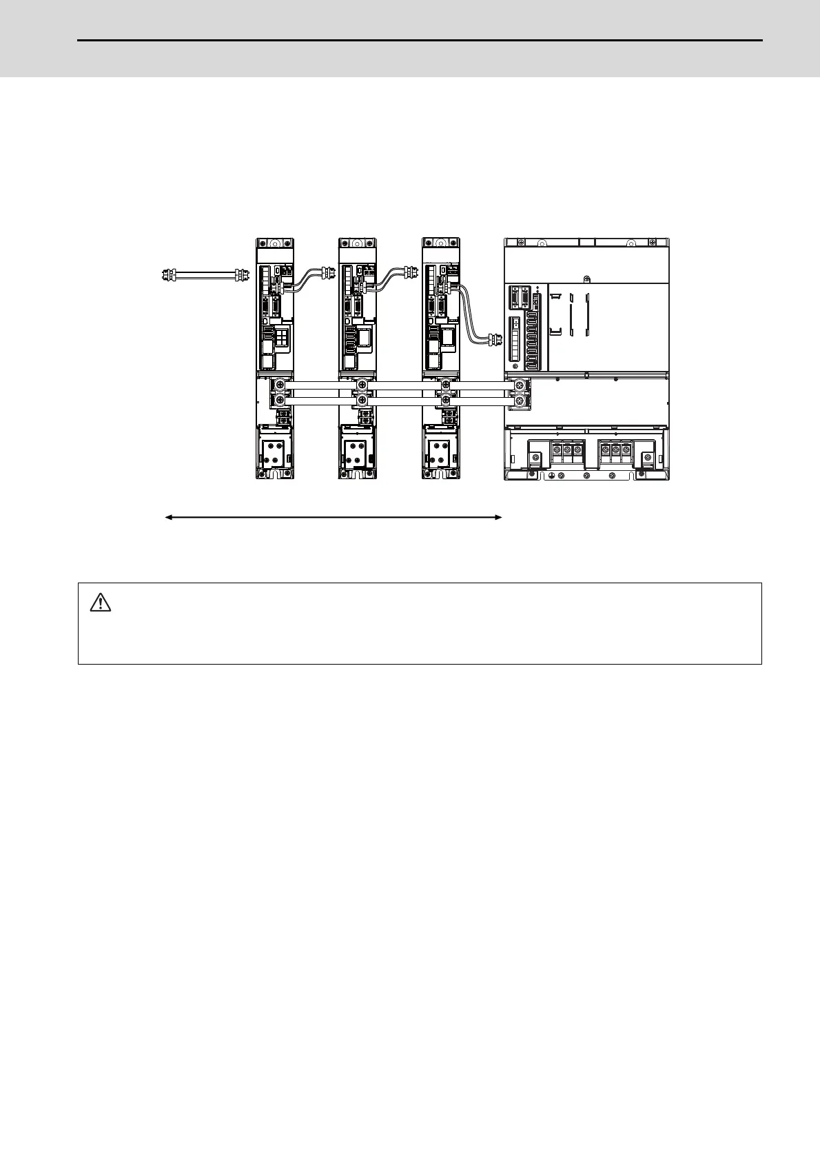
(2) When using the MDS-E/EH unit together
The power (L+, L-) can be supplied to the additional axis drive unit by using the power supply part which is built into
MDS-EM/EMH. For the additional axis unit receiving power (L+,L-) from the MDS-EM/EMH unit, the optical cable
must be connected at the NC side of the MDS-EM/EMH unit.
CAUTION
There is a limit to the combination of the drive unit.
Refer to "7.3 Selection of the Additional Axis Drive Unit" in "MDS-EM/EMH Series Specifications Manual".
MDS-EM-SPV3
MDS-E-V1 MDS-E-SP2 MDS-E-SP
TE2
The optical communication cables from the NC to the
final drive unit must be within 30m.
Optical
communication
cable
Connected
to the NC
5th axis 8th axis6th/7th axis
Servo:2nd/3rd/4th axis
Spindle:1st axis
When using MDS-EM drive unit together with MDS-E

 Loading...


