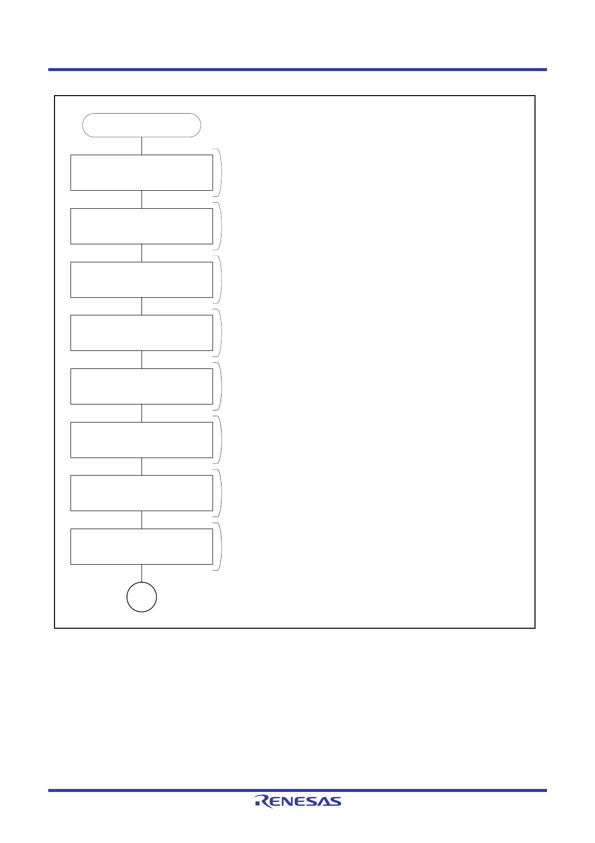
Start
Set 1 to ESMER.ESME
Set CR2.RTS[1:0], BCCS[1:0], and
DFCS[2:0]
Set PCR.SHARPS, RXDXPS, and
TXDXPS
SCI12 initialization
Set 1 to each bit in STCR
Set ICR.AEDIE, BCDIE, PIBDIE,
CF1MIE, CF0MIE, and BFDIE
Set TMR.TCSS[2:0]
Set TCNT and TPRE
Set 10b to TMR.TOMS[1:0]
Enable the extended serial mode control section.
Set the timing of sampling for RXDX12 reception, clock for bus collision detection,
and sampling clock for the RXDX12 signal’s digital filter.
Set the RXDX12 and TXDX12 pins.
Set Break Field low width output mode as the operating mode of the timer.
Set the clock source for counting and registers TCNT and TPRE to values that suit
the period for the Break Field low width.
Initialize SCI12 (refer to the example of a flowchart of SCI initialization
(asynchronous mode). However, set the SCR.TE bit to 1 and the SCR.RE bit to 0
for transmission and the SCR.TE bit to 0 and the SCR.RE bit to 1 for reception.
Data for output need not be set at this stage.
Clear all flags in the STR register.
Set interrupt-enable bits as required.
A

 Loading...