R01UH0823EJ0100 Rev.1.00 Page 527 of 1823
Jul 31, 2019
RX23W Group 23. Multi-Function Timer Pulse Unit 2 (MTU2a)
23.3.3 Buffer Operation
Buffer operation, provided for MTU0, MTU3, and MTU4, enables registers TGRC and TGRD to be used as buffer
registers. In MTU0, TGRF register can also be used as a buffer register.
Buffer operation differs depending on whether TGR has been designated as an input capture register or as a compare
match register.
Note: MTU0.TGRE register cannot be designated as an input capture register and can only operate as a compare
match register.
Table 23.40 shows the register combinations used in buffer operation.
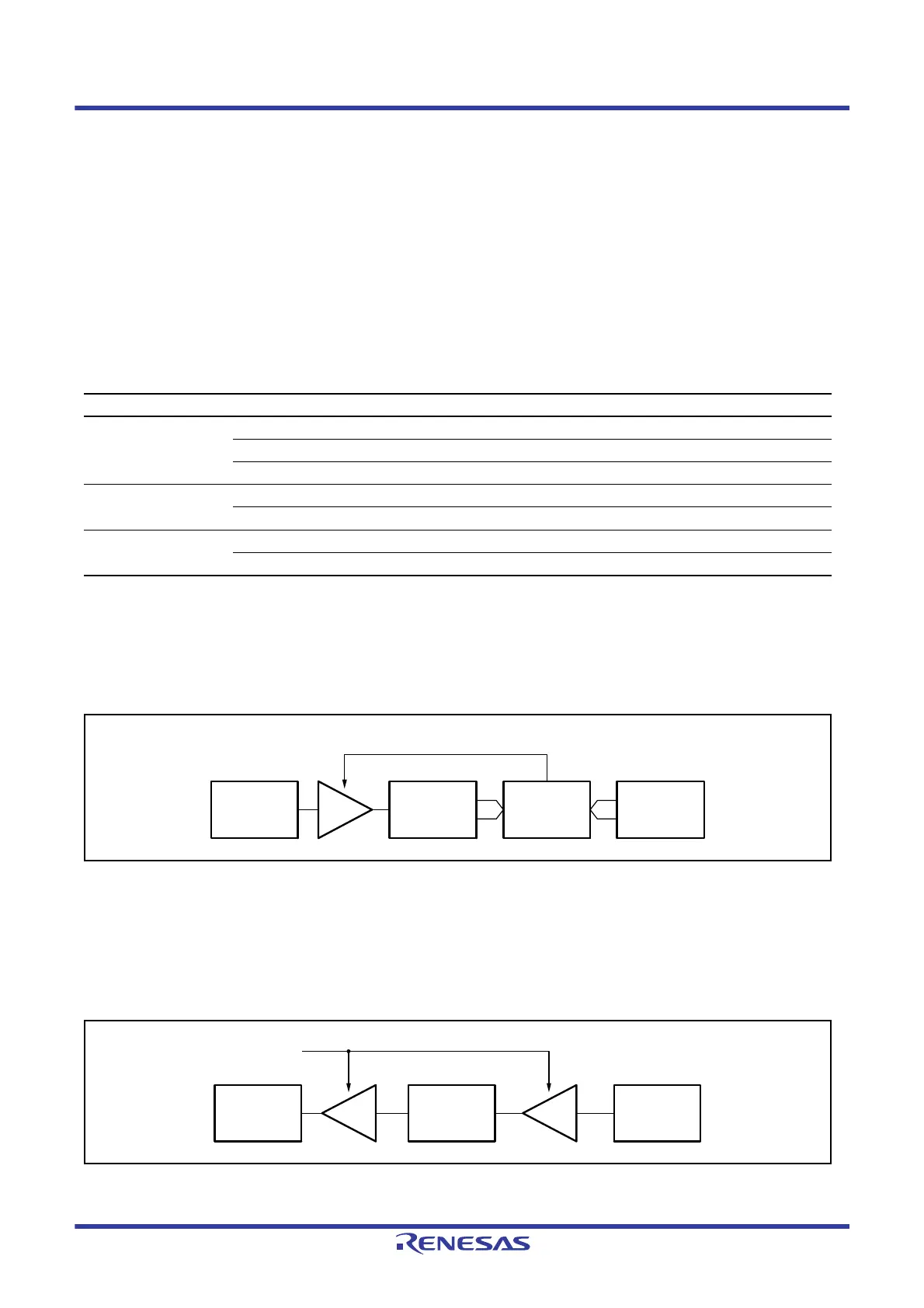
When TGR register is an output compare register
When a compare match occurs, the value in the buffer register for the corresponding channel is transferred to the timer
general register.
This operation is illustrated in
Figure 23.14.
Figure 23.14 Compare Match Buffer Operation
When TGR register is an input capture register
When an input capture occurs, the value in the TCNT counter is transferred to the TGR register and the value previously
held in the TGR register is transferred to the buffer register.
This operation is illustrated in
Figure 23.15.
Figure 23.15 Input Capture Buffer Operation
Table 23.40 Register Combinations in Buffer Operation
Channel Timer General Register Buffer Register
MTU0 TGRA TGRC
TGRB TGRD
TGRE TGRF
MTU3 TGRA TGRC
TGRB TGRD
MTU4 TGRA TGRC
TGRB TGRD
Compare match signal
Timer general
register
Comparator TCNT
Buffer
register
Input capture
signal
Buffer
register
Timer general
register
TCNT

 Loading...


