R01UH0823EJ0100 Rev.1.00 Page 1525 of 1823
Jul 31, 2019
RX23W Group 43. Capacitive Touch Sensing Unit (CTSU)
43.3.3 Items Common to Multiple Modes
43.3.3.1 Sensor Stabilization Wait Time and Measurement Time
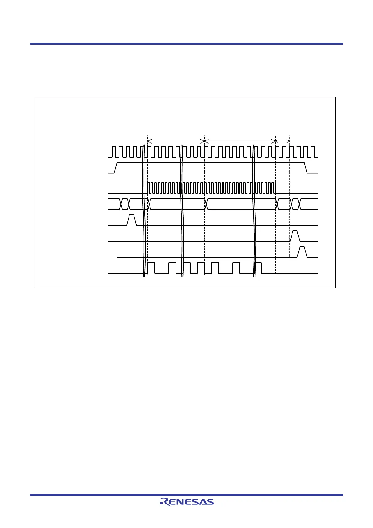
Figure 43.18 shows the timing chart of the sensor stabilization wait time and measurement time.
Figure 43.18 Sensor Stabilization Wait Time and Measurement Time
(1) In response to the CTSUWR interrupt request, output of the sensor drive pulse is started by write access to the
CTSUSO1 register. Then, wait for the stabilization time set in the CTSUSST register.
(2) When the sensor stabilization time has elapsed and the CTSUST.CTSUDTSR flag is set to 0, measurement is started
at transition to Status 4. The measurement time is determined by setting the base clock cycle and the
CTSUSDPRS.CTSUPRMODE[1:0], CTSUPRRATIO[3:0], and CTSUSO0.CTSUSNUM[5:0] bits. When the
measurement time has elapsed, measurement of the corresponding channel is finished.
(3) After the measurement time has elapsed, the status transitions to Status 1 after two operating clock cycles and a
CTSURD interrupt is generated, so read the data from the CTSUSC and CTSURC counters.
At this time, the sensor drive pulse is output at the low level. When measurement of all specified channels is
completed, the CTSUCR0.CTSUSTRT bit becomes 0.
(4) The sensor ICO clock oscillates while the CTSUSTC[2:0] flags are 011b (Status 3) or 100b (Status 4).
21
Sensor drive pulse
(1)
Sensor stabilization wait time
(CTSUSST register)
(2)
Measurement time
CTSUST.CTSUSTC[2:0]
flags (Status)
0 3 4 0
Operating clock
CTSUCR0.CTSUSTRT
bit
Sensor ICO clock
Sensor drive pulse
stop period
(3)
5
(4)
CTSUWR interrupt
CTSURD interrupt
1
CTSUFN interrupt

 Loading...


