R01UH0823EJ0100 Rev.1.00 Page 1088 of 1823
Jul 31, 2019
RX23W Group 33. Serial Communications Interface (SCIg, SCIh)
33.10.6 Bit Rate Measurement
The bit rate measurement function measures the intervals between rising and falling edges and between falling and rising
edges of the signal input from the RXDX12 pin.
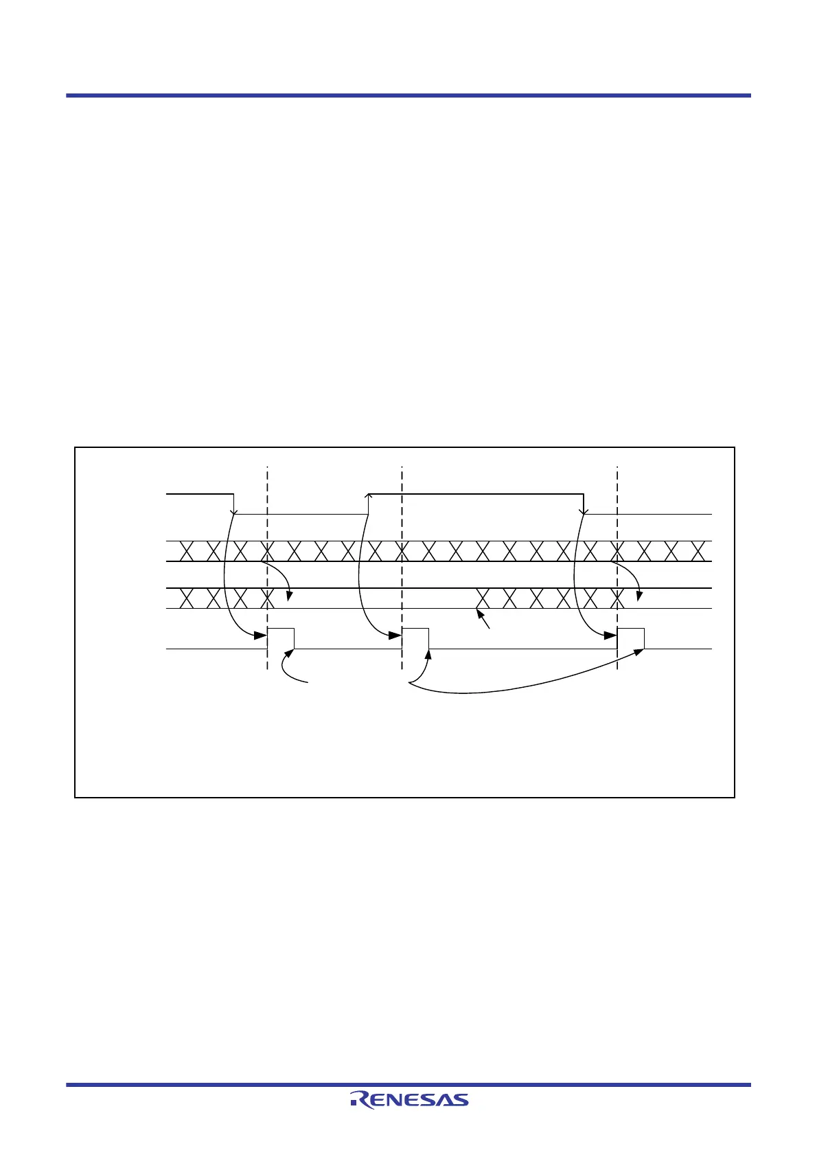
Figure 33.71 shows an example of operations for bit rate measurement.
(1) Writing 1 to the CR0.BRME bit enables bit rate measurement. Only set the BRME bit to 1 when you wish to
proceed with bit rate measurement. Furthermore, bit rate measurement will not proceed during a Break Field, even
if the BRME bit is set to 1.
(2) After detection of the Break Field low width, bit rate measurement starts when the level input on the RXDX12 pin
becomes high.
(3) Once bit rate measurement has started, counter values from the timer are retained in the read buffers on the input of
valid edges from the RXDX12 pin (rising and falling edges) and the counter is reloaded. An SCIX3 interrupt is also
generated if the value of the ICR.AEDIE bit is 1. Retention by registers TCNT and TPRE is released by reading
these registers.
(4) The bit rate as calculated from the values counted during intervals between valid edges can be used for adjusting the
rate by changing the settings of the BRR register. To disable the bit rate measurement after a match with Control
Field 1, write 0 to the CR0.BRME bit.
Figure 33.71 Example of Operations for Bit Rate Measurement
10 0F 0E 0D
11 10 0F 0E 0D
FF FE FD FC FF FE FD FCFB FB FA F9 F8
FD FC FB FA F9 F8
FF FE FDCounter value
RXDX12 pin
Read buffer*
1
STR.AEDF
Valid edge
Valid edge
Valid edge
Retained*
3
Write 1 to
STCR.AEDCL
Read the counter value*
5
Retention released Retained
Reload Reload Reload
*
2
*
4
Note 1. The TCNT or TPRE register indicates the contents of the read buffers.
Note 2. The STR.AEDF flag becomes 1 on detection of a valid edge.
Note 3. When an effective edge is detected, the current value of the counter is stored in the read buffer.
Note 4. The value retained in the read buffers due to one valid edge is not updated to the new value even if a further valid edge is detected.
Note 5. Retention of a value in a read buffer due to a valid edge is released by reading the TCNT or TPRE register.

 Loading...


