Discharge the external LPF capacitor connected to the MCU by using
the TSCAP pin as the I/O port function and driving it low for the specified time.
Set the corresponding pin to TSm (
m = 2, 3, 4, 7, 8, 12, 13, 22, 23, 27, 30, 35) by
setting the pin function select register of the multi-function pin controller (MPC)
(PijPFS = 11001b), and set the pin to the peripheral function by setting the
port mode register for the I/O port (PORTi.PMR.Bj = 1).
Enable this module clock by setting the MSTPD10 bit in module stop control
register D (MSTPCRD) to 0.
Set the CTSU power supply operating mode and capacity adjustment.
When operating the CTSU while VCC is lower than 2.4 V, set the
CTSUCR1.CTSUATUNE0 bit.
Set the CTSUCR1.CTSUATUNE1 bit according to electrostatic capacitance
generated in the electrode connected to the TS pin.
Use the CTSUCR1.CTSUCLK[1:0] and CTSUSO1.CTSUSDPA[4:0] bits to set
the base clock.
Supply power to the CTSU and connect the LPF capacitor to the TSCAP pin.
Write 1 to the CTSUCR1.CTSUPON bit and 1 to the CTSUCR1.CTSUCSW bit
at the same time.
After data is written, wait until charging of the external LPF capacitor
connected to the TSCAP pin stabilizes.
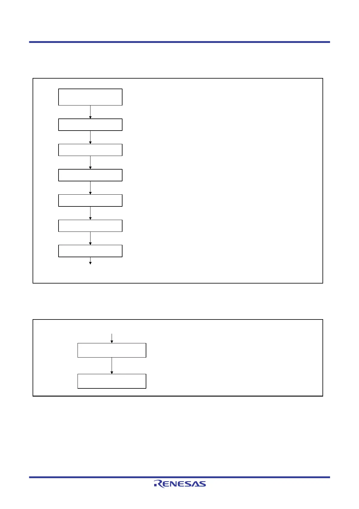
Power off CTSU
Disable this module clock by setting the MSTPD10 bit in
module stop control register D (MSTPCRD) to 1.
Enable module standby
CTSU operation completed
Power off the CTSU and disconnect the TSCAP pin
from the LPF capacitor.
Write 0 to the CTSUCR1.CTSUPON bit and
0 to the CTSUCR1.CTSUCSW bit.

 Loading...


