R01UH0823EJ0100 Rev.1.00 Page 602 of 1823
Jul 31, 2019
RX23W Group 23. Multi-Function Timer Pulse Unit 2 (MTU2a)
23.6.13 Counter Value When Count Operation is Stopped in Complementary PWM
Mode
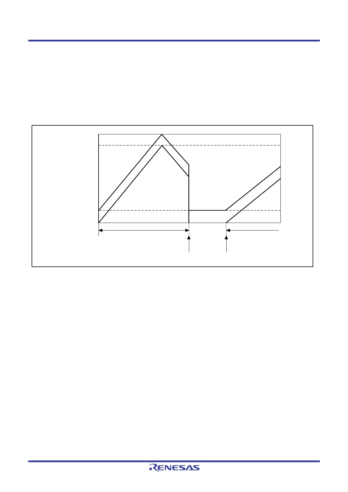
When counting operation in counters MTU3.TCNT and MTU4.TCNT is stopped in complementary PWM mode, the
MTU3.TCNT counter is set to the TDDR register value and the MTU4.TCNT counter becomes 0000h.
When operation is restarted in complementary PWM mode, counting begins automatically from the initial setting state.
Figure 23.106 shows this operation.
When counting begins in another operating mode, be sure to make initial settings in counters MTU3.TCNT and
MTU4.TCNT.
Figure 23.106 Counter Value When Stopped in Complementary PWM Mode (MTU3 and MTU4 Operation)
23.6.14 Buffer Operation Setting in Complementary PWM Mode
When modifying the PWM cycle set register (MTU3.TGRA), timer cycle data register (TCDR), and compare registers
(MTU3.TGRB, MTU4.TGRA, and MTU4.TGRB) in complementary PWM mode, be sure to use buffer operation. Also,
the MTU4.TMDR.BFA bit and MTU4.TMDR.BFB bit should be set to 0. Setting the MTU4.TMDR.BFA bit to 1
disables MTIOC4C pin waveform output. Setting the MTU4.TMDR.BFB bit to 1 also disables MTIOC4D pin waveform
output.
In complementary PWM mode, buffer operation in MTU3 and MTU4 depends on the settings in bits BFA and BFB in
the MTU3.TMDR register. When the MTU3.TMDR.BFA bit is set to 1, the MTU3.TGRC register functions as a buffer
register for the MTU3.TGRA register. At the same time, the MTU4.TGRC register functions as a buffer register for the
MTU4.TGRA register, and the TCBR register functions as a buffer register for the TCDR register.
Complementary PWM
mode operation
Complementary PWM restartCounter operation stop
Complementary PWM mode operation
0000h
TDDR
TCDR
MTU3.TGRA
MTU3.TCNT
MTU4.TCNT

 Loading...


