R01UH0823EJ0100 Rev.1.00 Page 506 of 1823
Jul 31, 2019
RX23W Group 23. Multi-Function Timer Pulse Unit 2 (MTU2a)
23.2.18 Timer Output Control Registers 2 (TOCR2)
Note 1. Setting the TOCR1.TOCS bit to 1 makes this bit setting valid.
Note 2. If dead-time is not generated, the negative-phase output is always the exact inverse of the positive-phase output. In these
cases, only the OLSiP bits are valid (i = 1 to 3).
The TOCR2 registers control inversion of PWM output level in complementary PWM mode and reset-synchronized
PWM mode.
Note: The initial output value of negative-phase waveform changes to an active level after the dead time has passed since counting
starts.
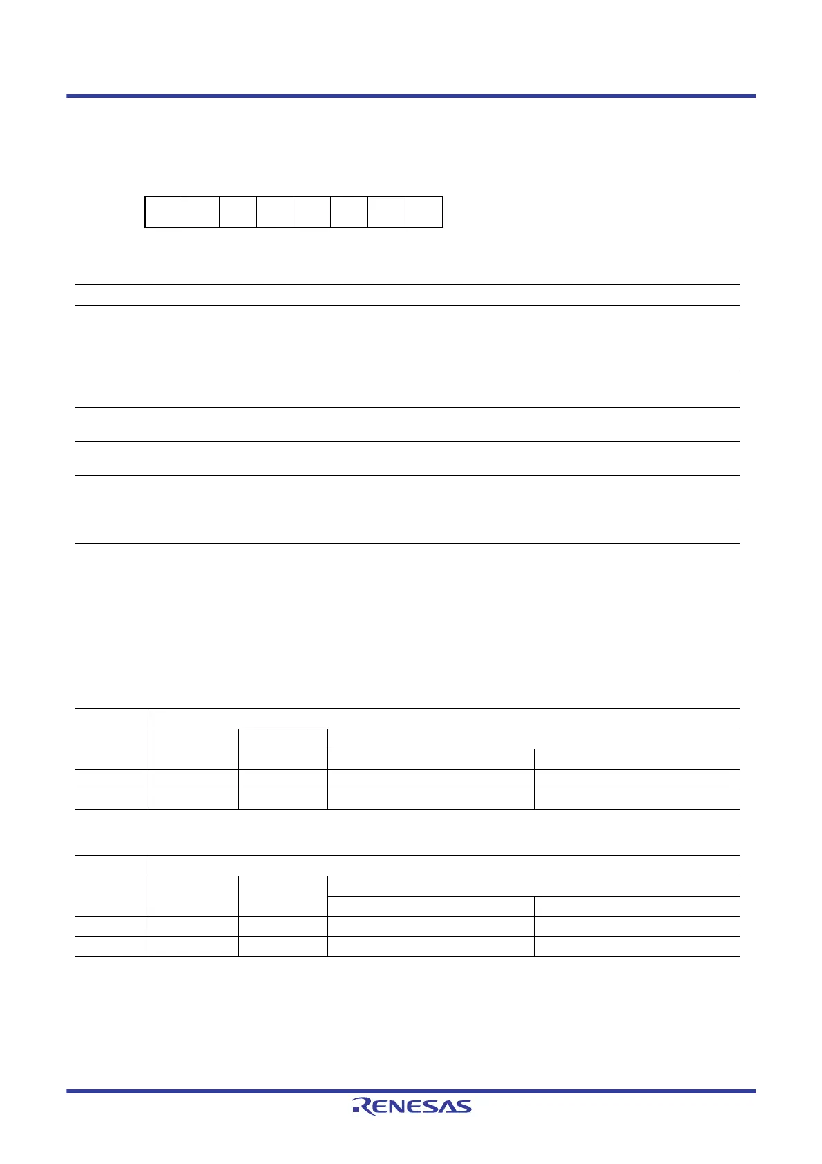
Address(es): MTU.TOCR2 000D 0A0Fh
b7 b6 b5 b4 b3 b2 b1 b0
BF[1:0] OLS3N OLS3P OLS2N OLS2P OLS1N OLS1P
Value after reset:
00000000
Bit Symbol Bit Name Description R/W
b0 OLS1P Output Level Select 1P*
1,
*
2
This bit selects the output level on MTIOC3B in reset-synchronized
PWM mode and complementary PWM mode. Refer to Table 23.29.
R/W
b1 OLS1N Output Level Select 1N*
1,
*
2
This bit selects the output level on MTIOC3D in reset-synchronized
PWM mode and complementary PWM mode. Refer to Table 23.30.
R/W
b2 OLS2P Output Level Select 2P*
1,
*
2
This bit selects the output level on MTIOC4A in reset-synchronized
PWM mode and complementary PWM mode. Refer to Table 23.31.
R/W
b3 OLS2N Output Level Select 2N*
1,
*
2
This bit selects the output level on MTIOC4C in reset-synchronized
PWM mode and complementary PWM mode. Refer to Table 23.32.
R/W
b4 OLS3P Output Level Select 3P*
1,
*
2
This bit selects the output level on MTIOC4B in reset-synchronized
PWM mode and complementary PWM mode. Refer to Table 23.33.
R/W
b5 OLS3N Output Level Select 3N*
1,
*
2
This bit selects the output level on MTIOC4D in reset-synchronized
PWM mode and complementary PWM mode. Refer to Table 23.34.
R/W
b7, b6 BF[1:0] TOLBR Buffer Transfer Timing
Select
These bits select the timing for transferring data from TOLBR to
TOCR2. Refer to Table 23.35 for details.
R/W
Table 23.29 MTIOC3B Output Level Select Function
Bit 0 Function
OLS1P Initial Output Active Level
Compare Match Output
Up-Counting Down-Counting
0 High Low Low High
1 Low High High Low
Table 23.30 MTIOC3D Output Level Select Function
Bit 1 Function
OLS1N Initial Output Active Level
Compare Match Output
Up-Counting Down-Counting
0 High Low High Low
1 Low High Low High

 Loading...


