R01UH0823EJ0100 Rev.1.00 Page 1045 of 1823
Jul 31, 2019
RX23W Group 33. Serial Communications Interface (SCIg, SCIh)
33.5.5 Serial Data Reception (Clock Synchronous Mode)
Figure 33.29 and Figure 33.30 show an example of SCI operation for serial reception in clock synchronous mode.
In serial data reception, the SCI operates as described below.
1. The value of the RE bit in the SCR register becoming 1 places the signal output on the RTSn# pin at the low level
(when the RTS function is in use).
2. The SCI performs internal initialization and starts receiving data in synchronization with a synchronization clock
input or output, and stores the receive data in the RSR register.
3. If an overrun error occurs, the ORER flag in the SSR register is set to 1. If the RIE bit in the SCR register is 1 at this
time, an ERI interrupt request is generated. Receive data is not transferred to the RDR register.
4. When reception finishes successfully, receive data is transferred to the RDR register. If the RIE bit in the SCR
register is 1 at this time, an RXI interrupt request is generated. Continuous reception is enabled by reading the
receive data transferred to the RDR register in this RXI interrupt handling routine before reception of the next
receive data is completed. Reading out the received data that have been transferred to the RDR register causes the
RTSn# pin to output the low level (when the RTS function is in use).
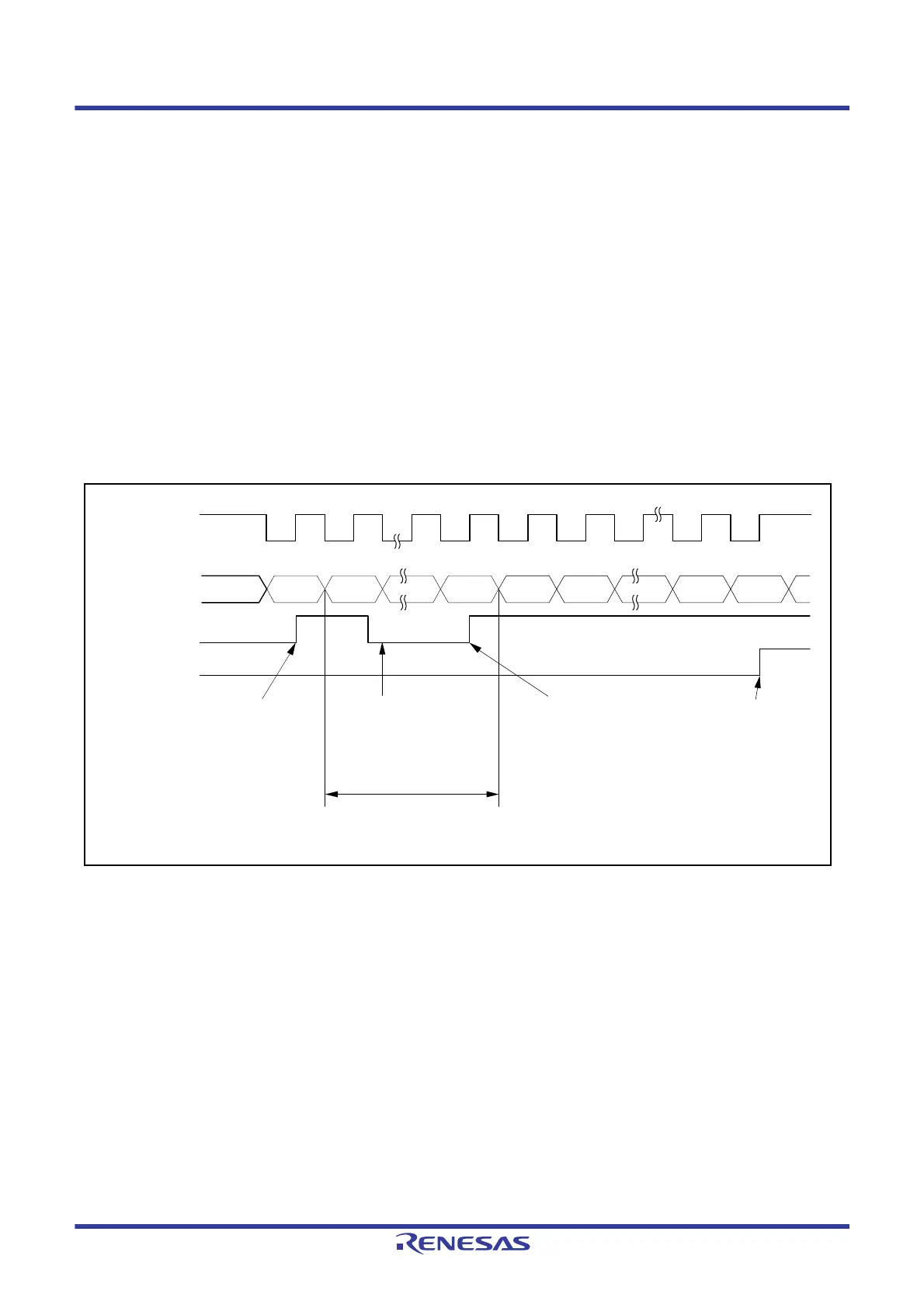
Figure 33.29 Example of Operation for Serial Reception in Clock Synchronous Mode (1)
(When RTS Function is Not Used)
1 frame
RXI interrupt flag
(IRn in ICU*
1
)
SSR.ORER flag
Bit 7 Bit 0 Bit 7 Bit 0 Bit 1 Bit 7Bit 6
RDR data read in RXI
interrupt handling routine
RXI interrupt
request
generated
RXI interrupt
request
generated
ERI interrupt request
generated by overrun error
Synchronization
clock
Serial data
Note 1. Refer to section 15, Interrupt Controller (ICUb) for details on the corresponding interrupt vector number.

 Loading...


