R01UH0823EJ0100 Rev.1.00 Page 1099 of 1823
Jul 31, 2019
RX23W Group 33. Serial Communications Interface (SCIg, SCIh)
33.14.6 Restrictions on Clock Synchronous Transmission (Clock Synchronous Mode
and Simple SPI Mode)
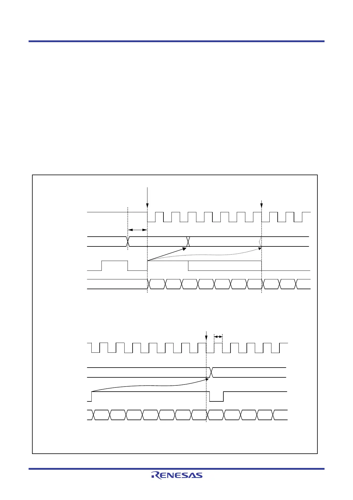
When the external clock source is used as a synchronization clock, the following restrictions apply.
(1) Start of transmission
Update TDR by the CPU, DMAC, or DTC and wait for at least five PCLK cycles before allowing the transmit clock to
be input (refer to
Figure 33.76).
(2) Continuous transmission
(a) Write the next transmit data to TDR or TDRL before the falling edge of the transmit clock (bit 7) (refer to Figure
33.76
).
(b) When updating TDR after bit 7 has started to transmit, update TDR while the synchronization clock is in the
low-level period, and set the high-level width of the transmit clock (bit 7) to four PCLK cycles or longer (refer to
Figure 33.76).
Figure 33.76 Restrictions on Use of External Clock in Clock Synchronous Transmission
D0 D1 D3 D4 D5 D7 D0
D2
D6
Synchronous clock
(external clock)
Serial transmit data
TXI interrupt flag
(ICU.IRn
*1
)
(1) Start of transmission and (2) Continuous transmission (a)
D0 D1 D3 D4 D5 D7 D0
D2
D6
Update TDR before bit 7 is started to transmit when
continuous transmission is performed on the external clock.
TDR
t
First frame of data
Next frame of data
Synchronous clock
(external clock)
Serial transmit data
TXI interrupt flag
(ICU.IRn
*1
)
(2) Continuous transmission (b)
TDR
Previous frame of data
Next frame of data
D1 D2
t
D1
D3
Set t 5 cycles of the PCLK before transmission is started when the external clock is used.
Set t
4 cycles of the PCLK if TDR is updated after bit 7 is started to transmit when continuous
transmission is performed on the external clock.
Note 1. Refer to section 15, Interrupt Controller (ICUb) for details on the corresponding interrupt vector number.

 Loading...


