R01UH0823EJ0100 Rev.1.00 Page 653 of 1823
Jul 31, 2019
RX23W Group 24. Port Output Enable 2 (POE2a)
24.3.1 Input Level Detection Operation
If the input conditions set by the ICSR1 and ICSR2 registers occur on the POE0# to POE3# and POE8# pins, the pins for
the MTU complementary PWM output and MTU0 are placed in high-impedance.
(1) Falling Edge Detection
When a change from a high to low level is input to the POE0#, POE1#, POE3# and POE8# pins, the pins for the MTU
complementary PWM output and MTU0 are placed in high-impedance.
A falling edge is detected after PCLK causes sampling to proceed. If the low level is input to the POE0#, POE1#, POE3#
or POE8# pin over less than one PCLK cycle, whether the falling edge will or will not be detected cannot be guaranteed.
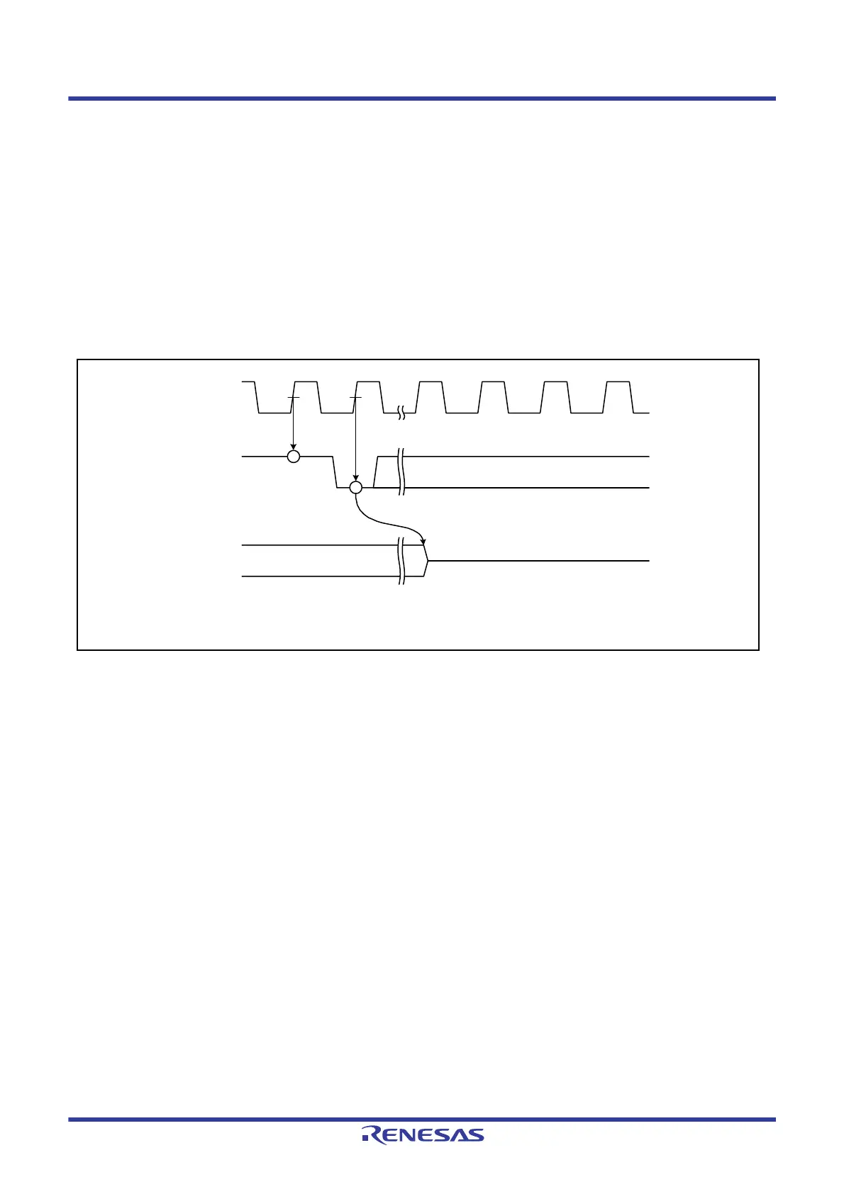
Figure 24.2 shows the timing of sampling after the level changes in input to the POE0#, POE1#, POE3# and POE8#
pins until the respective pins enter high-impedance.
Figure 24.2 Falling Edge Detection
PCLK
POE# input
MTIOC3B
PCLK rising edge
Falling edge detection
High-impedance*
1
Note 1. The other MTU complementary PWM output pins and MTU0 pins also enter
the high-impedance in the similar timing.

 Loading...


