R01UH0823EJ0100 Rev.1.00 Page 1590 of 1823
Jul 31, 2019
RX23W Group 44. 12-Bit A/D Converter (S12ADE)
44.3.3.2 Channel Selection and Self-Diagnosis
When channels and self-diagnosis are selected at the same time, A/D conversion is first performed for the reference
voltage VREFH0 supplied to the 12-bit A/D converter, and then A/D conversion is performed on the analog input of the
selected channels, which sequence is repeated as below. In continuous scan mode, the temperature sensor output A/D
conversion select bit (ADEXICR.TSSA) and the internal reference voltage A/D conversion select bit
(ADEXICR.OCSA) should be set to 0 (deselected).
(1) When the ADCSR.ADST bit is set to 1 (A/D conversion start) by software, synchronous trigger, or asynchronous
trigger input, A/D conversion for self-diagnosis is started first.
(2) When A/D conversion for self-diagnosis is completed, the A/D conversion result is stored into the A/D self-
diagnosis data register (ADRD). A/D conversion is then performed for ANn channels selected by the ADANSA0
and ADANSA1 registers, starting from the channel with the smallest number n.
(3) Each time A/D conversion of a single channel is completed, the A/D conversion result is stored into the
corresponding A/D data register (ADDRy).
(4) When A/D conversion of all the selected channels is completed, an S12ADI0 interrupt request is generated if the
ADCSR.ADIE bit is 1 (S12ADI0 interrupt upon scanning completion enabled). At the same time, the 12-bit A/D
converter starts A/D conversion for self-diagnosis and then starts A/D conversion on ANn channels selected by the
ADANSA0 and ADANSA1 registers, starting from the channel with the smallest number n.
(5) The ADST bit is not automatically cleared and steps 2 to 4 are repeated as long as the bit remains 1. When the
ADST bit is set to 0 (A/D conversion stop), A/D conversion stops and the 12-bit A/D converter enters a wait state.
(6) When the ADST bit is later set to 1 (A/D conversion start), the A/D conversion for self-diagnosis is started again.
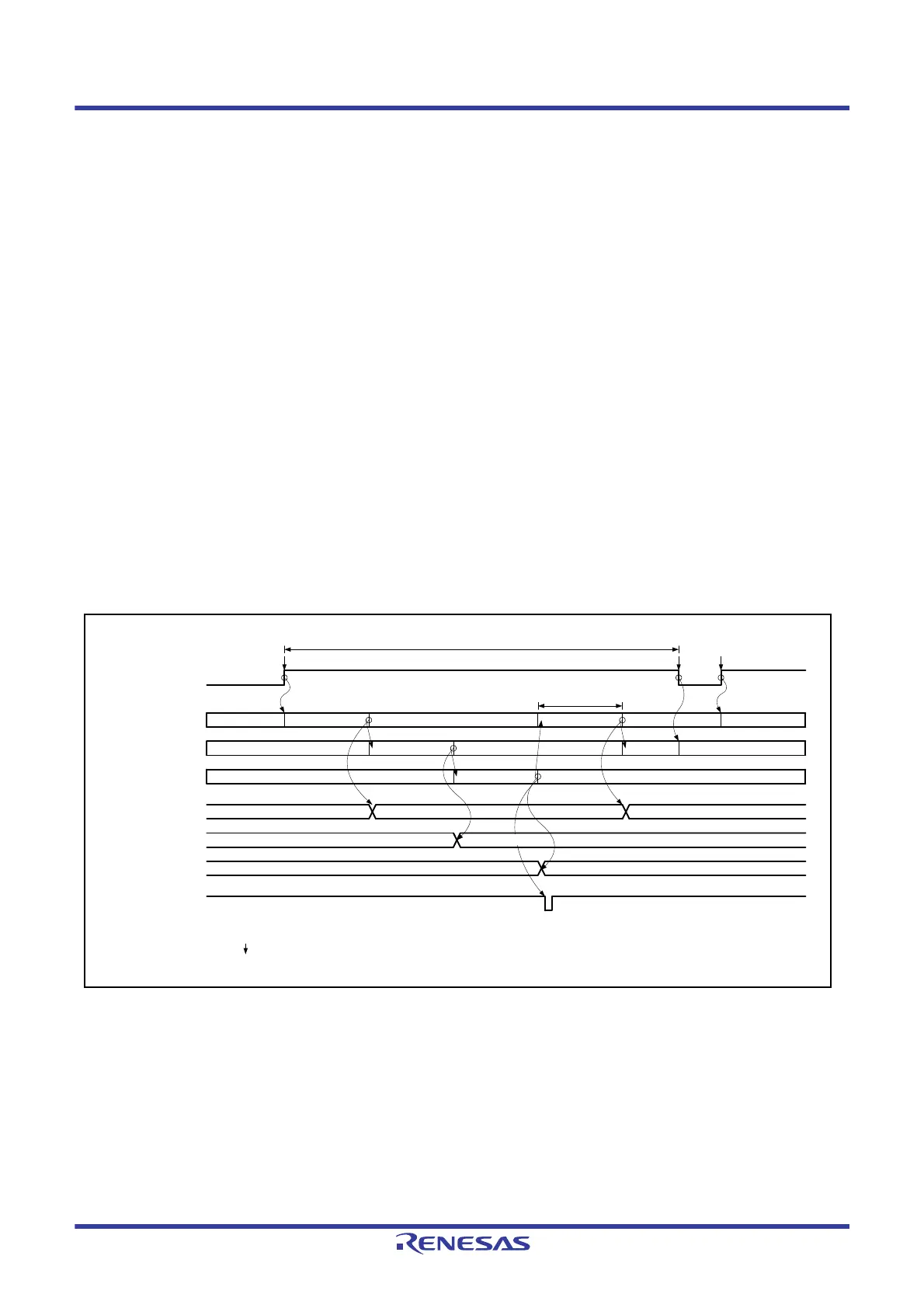
Figure 44.10 Example of Operation in Continuous Scan Mode (Basic Operation; AN001 and AN002 Selected +
Self-Diagnosis)
ADST
A/D conversion
started
Reference voltage
(×0, ×½, ×1)
Waiting for
conversion
Channel 1
(AN001)
Waiting for conversion
Channel 2
(AN002)
ADRD
ADDR1
ADDR2
A/D conversion for self-
diagnosis 1
Set
(1)
Stored
A/D conversion 1
Waiting for conversion
Waiting for conversion
A/D conversion
3
*2
Clear
(6)
Waiting for conversion
A/D conversion 2
A/D conversion for self-diagnosis
result 1
Waiting for
conversion
Waiting for conversion
A/D conversion result 2
A/D
conversion time
Self-diagnosis and scanning performed repeatedly
(2)
(3)
Set
(5)
A/D conversion for self-
diagnosis 2
A/D conversion for self-
diagnosis 3
A/D conversion for self-diagnosis
result 2
(3)
Interrupt generated
A/D conversion result 1
(4)
(2)
*1
Waiting for conversion
Stored
Note 1. indicates the instruction is executed by software.
Note 2. The converted data of A/D conversion 5 is ignored.

 Loading...


