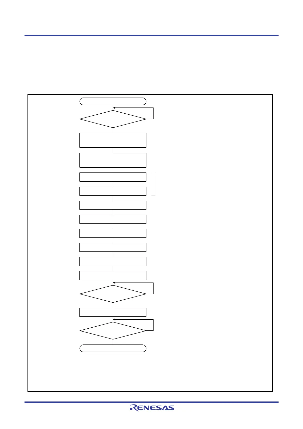
Start
Is the GSTS.GRAMINIT flag 0?
Is transition to
global operating mode
completed?
*1
Is transition to
channel communication mode
completed?
*2, *3
End
Transition from global stop mode to
global reset mode
(Set the GCTRL.GSLPR bit to 0)
Transition from channel stop mode to
channel reset mode
(Set the CTRL.CSLPR bit to 0)
Setting of GCFGH and GCFGL registers
Setting of CFGH and CFGL registers
Receive rule setting
Buffer setting
GCTRL register setting
CTRL register setting
Interrupt setting
Transition to global operating mode
*1
Transition to channel communication
mode
*2
Yes
No
Yes
No
Yes
No
• Clock
• Bit timing
• Communication speed
• Timestamp
• Mirror function
• DLC filter
• Transmit priority
GAFLCFG register,
GAFLIDLj, GAFLIDHj, GAFLMLj, GAFLMHj, and
GAFLPLj, GAFLPHj register
Receive buffer, receive FIFO buffer, transmit/receive
FIFO buffer, transmit buffer, transmit history buffer
Global interrupt
Channel interrupt, bus off recovery, error indication
Interrupt control registers of interrupt controller
Note 1. When global mode is changed by the GCTRL.GSLPR and GMDC[1:0] bits, use the GSTS register to confirm that the mode is switched.
Do not modify the GCTRL.GMDC[1:0] bits until the mode is switched.
Note 2. When channel mode is changed by the CTRL.CSLPR and CHMDC[1:0] bits, use the STSL register to confirm that the mode is switched.
Do not modify the CTRL.CHMDC[1:0] bits until the mode is switched.
Note 3. After the channel transitions to channel communication mode, when 11 consecutive recessive bits have been detected, communication is
ready (the STSL.COMSTS flag becomes 1) and transmission and reception are enabled on the CAN network as an active node. At this
time, transmission and reception of messages can be started.

 Loading...


