R01UH0823EJ0100 Rev.1.00 Page 536 of 1823
Jul 31, 2019
RX23W Group 23. Multi-Function Timer Pulse Unit 2 (MTU2a)
23.3.5 PWM Modes
PWM modes are provided to output PWM waveforms from the external pins. The output level can be selected as low,
high, or toggle output in response to a compare match of each TGR register.
PWM waveforms in the range of 0% to 100% duty cycle can be output according to the TGR settings.
By designating TGR compare match as the counter clearing source, the PWM cycle can be specified in that register.
Every channel can be set to PWM mode independently. Channels set to PWM mode can perform synchronous operation
with each other or other channels set to any other mode.
There are two PWM modes as described below.
(a) PWM Mode 1
PWM waveforms are output from the MTIOCnA and MTIOCnC pins by pairing the TGRA register with the TGRB
register and the TGRC register with the TGRD register. The levels specified by the TIOR.IOA[3:0] and IOC[3:0] bits are
output from the MTIOCnA and MTIOCnC pins at compare matches A and C, and the levels specified by the
TIOR.IOB[3:0] and IOD[3:0] bits are output at compare matches B and D. The initial output value is set in the TGRA
register or the TGRC register. If the values set in paired TGRs are identical, the output value does not change even when
a compare match occurs.
In PWM mode 1, up to eight phases of PWM waveforms can be output.
(b) PWM Mode 2
PWM output is generated using one TGR register as the cycle register and the others as duty registers. The level
specified in the TIOR register is output at compare matches. Upon counter clearing by a cycle register compare match,
the initial value set in the TIOR register is output from each pin. If the values set in the cycle and duty registers are
identical, the output value does not change even when a compare match occurs.
In PWM mode 2, up to eight phases of PWM waveforms can be output when using synchronous operation in
combination.
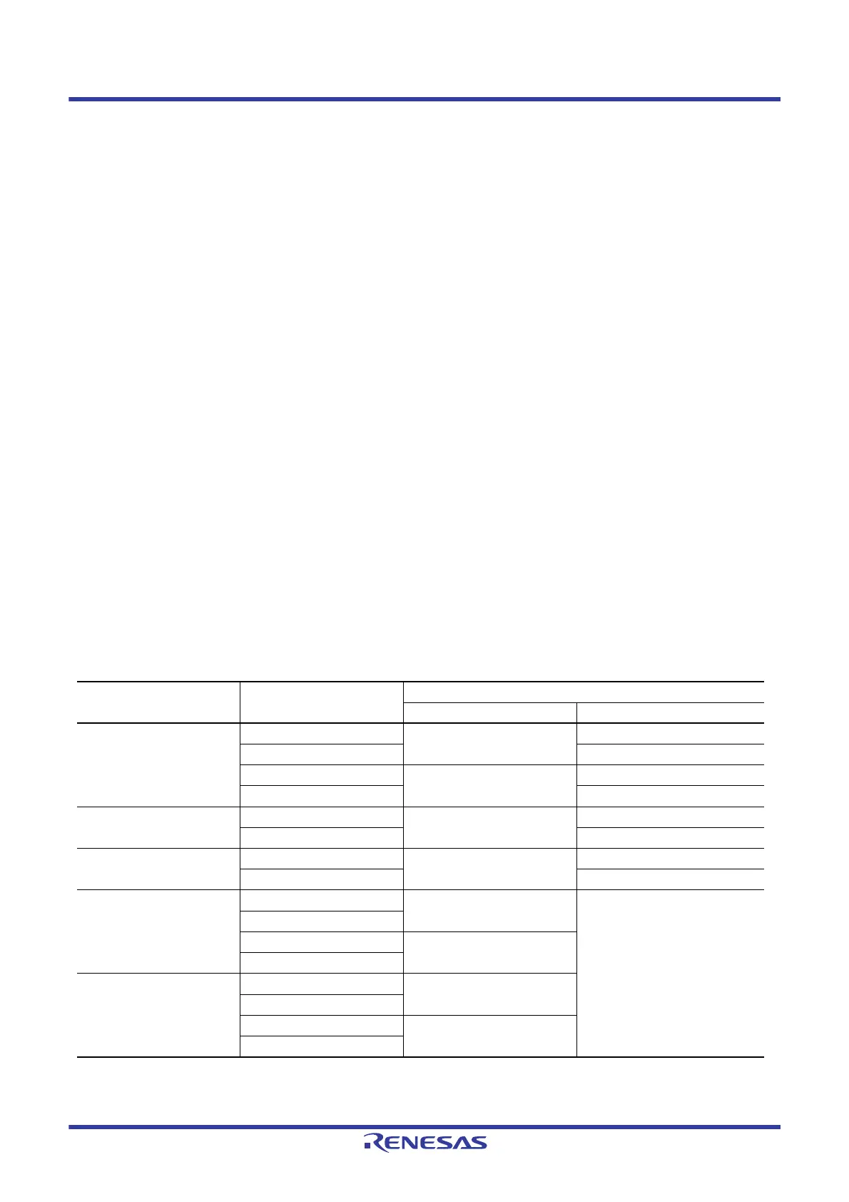
The correspondence between PWM output pins and registers is listed in
Table 23.43.
Note: In PWM mode 2, PWM output is not possible for the TGR register in which the PWM cycle is set.
Table 23.43 PWM Output Registers and Output Pins
Channel Register
Output Pins
PWM Mode 1 PWM Mode 2
MTU0 MTU0.TGRA MTIOC0A MTIOC0A
MTU0.TGRB MTIOC0B
MTU0.TGRC MTIOC0C MTIOC0C
MTU0.TGRD No pin is assigned for this output.
MTU1 MTU1.TGRA MTIOC1A MTIOC1A
MTU1.TGRB MTIOC1B
MTU2 MTU2.TGRA MTIOC2A MTIOC2A
MTU2.TGRB MTIOC2B
MTU3 MTU3.TGRA MTIOC3A Setting prohibited
MTU3.TGRB
MTU3.TGRC MTIOC3C
MTU3.TGRD
MTU4 MTU4.TGRA MTIOC4A
MTU4.TGRB
MTU4.TGRC MTIOC4C
MTU4.TGRD

 Loading...


