R01UH0823EJ0100 Rev.1.00 Page 1046 of 1823
Jul 31, 2019
RX23W Group 33. Serial Communications Interface (SCIg, SCIh)
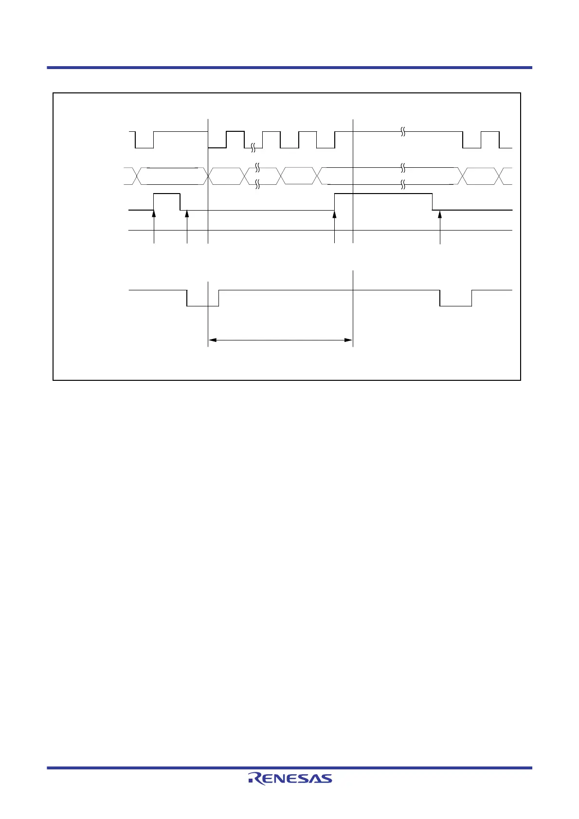
Figure 33.30 Example of Operation for Serial Reception in Clock Synchronous Mode (2) (When RTS Function
is Used)
Data transfer cannot be resumed while a receive error flag is 1. Accordingly, clear the ORER, FER, and PER flags in the
SSR register to 0 before resuming reception. Moreover, be sure to read the RDR register during overrun error processing.
When a reception is forcibly terminated by setting the SCR.RE bit to 0 during operation, read the RDR register because
received data which has not yet been read may be left in the RDR register.
1 frame
RXI interrupt flag
(IRn in ICU*
1
)
SSR.ORER flag
Bit 7 Bit 0 Bit 7 Bit 0
RDR data read in RXI
interrupt handling
routine
RXI interrupt
request
generated
RXI interrupt
request
generated
Synchronization
clock
Serial data
RTSn# pin
Bit 6
RDR data read in RXI
interrupt handling routine
Note 1. Refer to section 15, Interrupt Controller (ICUb) for details on the corresponding interrupt vector number.

 Loading...


