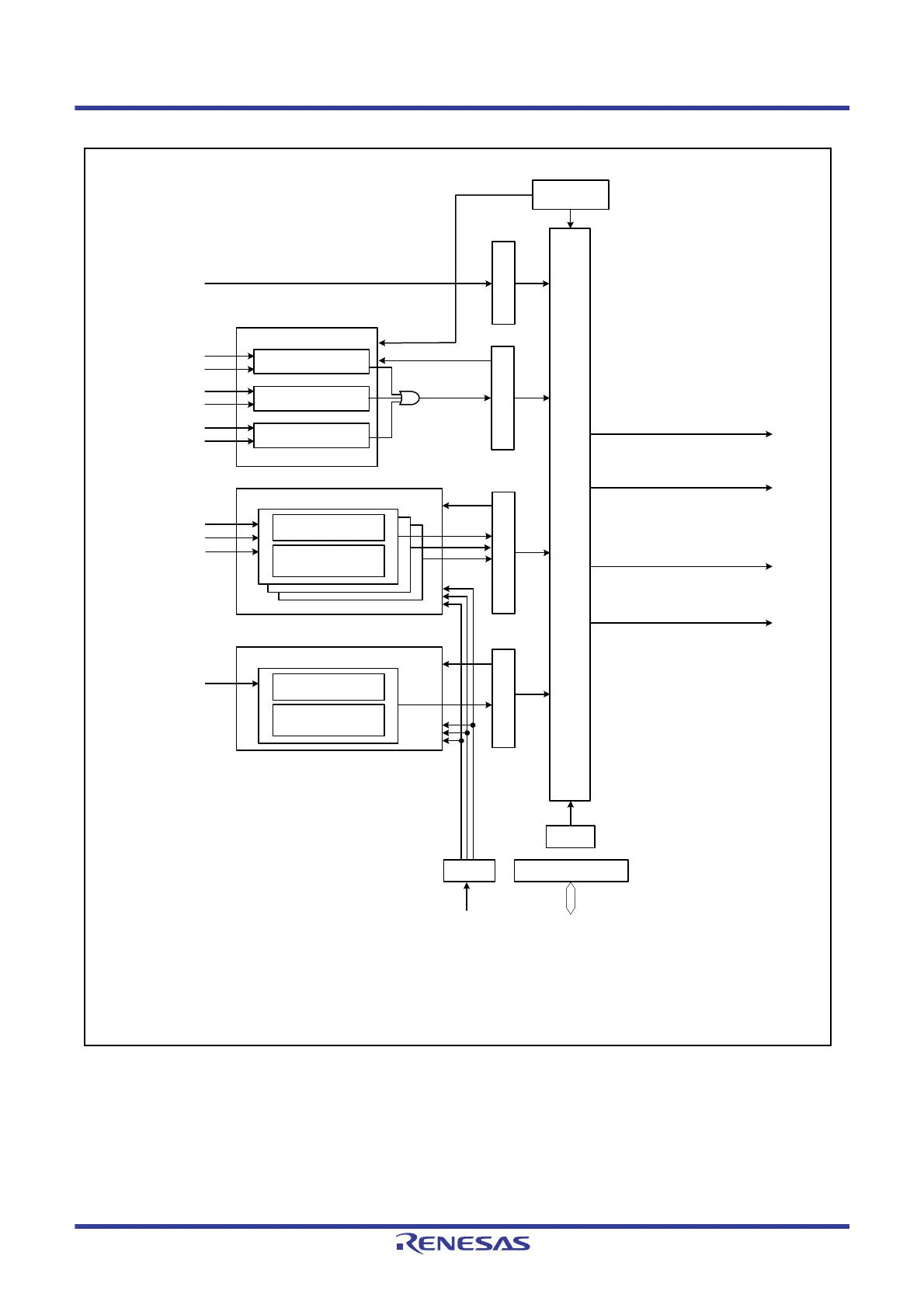
ICSR3ICSR1
Input level detection circuit
Falling edge detection
circuit
Low level
sampling circuit
POE3#
POE1#
POE0#
ICSR2
Input level detection circuit
POE8#
POECR1
POECR2
High-impedance request/interrupt request generation circuit
MTIOC3B
MTIOC4A
MTIOC4C
MTIOC4B
MTIOC4D
OCSR1
MTIOC3D
Low level
sampling circuit
ICSR1:
ICSR2:
ICSR3:
OCSR1:
SPOER:
POECR1:
POECR2:
Input level control/status register 1
Input level control/status register 2
Input level control/status register 3
Output level control/status register 1
Software port output enable register
Port output enable control register 1
Port output enable control register 2
Falling edge detection
circuit
OSTST
PCLK
Divider
SPOER
PCLK/8
PCLK/16
PCLK/128
Output level
comparison circuit
Output level
comparison circuit
Output level
comparison circuit
High-impedance request signal
for MTU3 and MTU4 pins
High-impedance request signal
for MTU0 pins
Interrupt request signal OEI1
Interrupt request signal OEI2
Oscillation stop detection signal
from the clock generation circuit
Bus interface
Internal peripheral bus

 Loading...


